Week-7 Challenge: DC Motor Control
1.
a. aim:
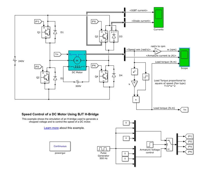
to explain a MATLAB demo model named ‘Speed control of a DC motor using BJT H-bridge’
explanation:
simulink block diagram of the model:
working:
1. BJT( bipolar junction diode) connected parallel to the diode operated as the IGBT switch in the power application or control
2.IGBT is power control switch which can operate at high currents and voltages
3 . these IGBT switches or operated by the simulink signels as shown in the block diagram
4. a DC motor is used in the model of capasity (5 HP 24V 1750 rpm).this motor can be operated between the voltage upto 240 v
5. H - bridge is a circuit where four IGBT switches are connected in a h format as shown in the above block diagram
6. in each of the contolling signel two IGBT switches are operated (Q1&Q4 OR Q2&Q3 )
7. when Q1&Q4 are operated positve voltage is supplied to the dc motor where Q2&Q3 are set to switch off
8. when Q2&Q3 are operated negative voltage is supplied to the dc motor where Q1&Q4 are set to switch off
output:
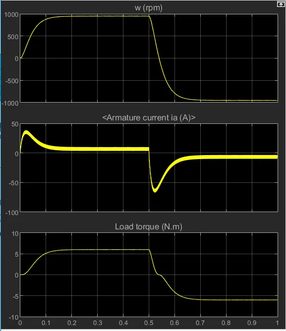
The motor starts in the positive direction with a duty cycle of 75% (mean DC voltage of 180V). At t= 0.5 sec., the armature voltage is suddenly reversed and the motor runs in the negative direction.'Scope' shows motor speed, armature current and load torque and 'Currents' shows currents flowing in BJT Q3 and diode D3.
b. Comment on the armature current shoot-up from the scope results
from the previous simulation of the model we can observe with the duty cycle of 75% with a armature current shoot up as below 50 A in negative direction
case 1:
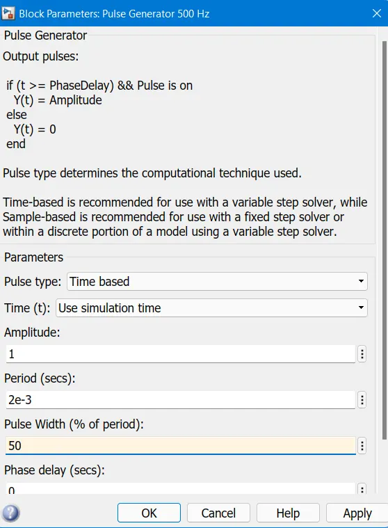
change the duty cycle to 50 % plot the results
result:
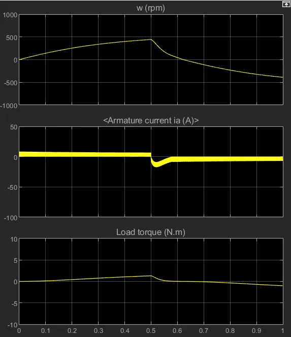
with the decrease in the duty cycle to 50% from the 75% we can decrese the shoot up of armature current .with the further decrement of the duty cycle futher we can observe further shoot up in the armature current.
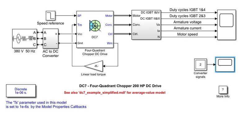
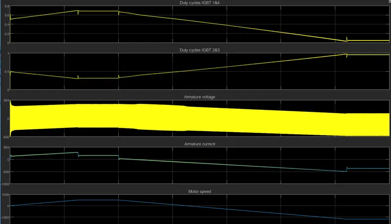
c. to Refer to the help section of ‘The Four-Quadrant Chopper DC Drive (DC7) block’. Compare it with the H-bridge model.
simulink block diagram of the model:
result:
comparison of The Four-Quadrant Chopper DC Drive (DC7) with H Bridge
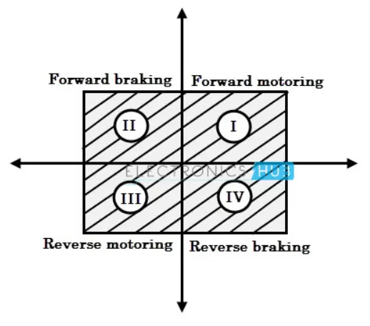
1. The Four-Quadrant Chopper DC Drive (DC7) can be operated in four possible switching condtions such as forward motoring ,farword regenerative braking, reverse motoring , reverse braking where H-bridge is only operated in forward motoring and reverse motoring
2. chopper switches are mostly used in industrial applications such as huge power drawn applications, H-bridge systems are used for electric vehicle applications
3. maintance of H bridge circuits are less than that of chopper circuits as these are run by signel modulation where as choppers are operated individually
4.The Four-Quadrant Chopper DC Drive (DC7) work more efficiently than the h-bridge as frequency is more when compared to H bridge circuits.
5. mode of operation of H bridge is better than the Four-Quadrant Chopper DC Drive (DC7) managing and changing the signels is complicated.
2.
aim:
to Develop a 2-quadrant chopper using simulink & explain the working of the same with the relevant results.
explanation:
As we know that, a class A and class B choppers operates in first and second quadrant respectively. Therefore, if we connect both these types of chopper in parallel then it is possible to have chopper operation in first as well as second quadrant.
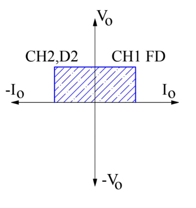
In fact, Class-C or Type-C chopper is obtained by the parallel connection of Class-A and Class-B chopper. Figure below shows the circuit diagram of this type of chopper.
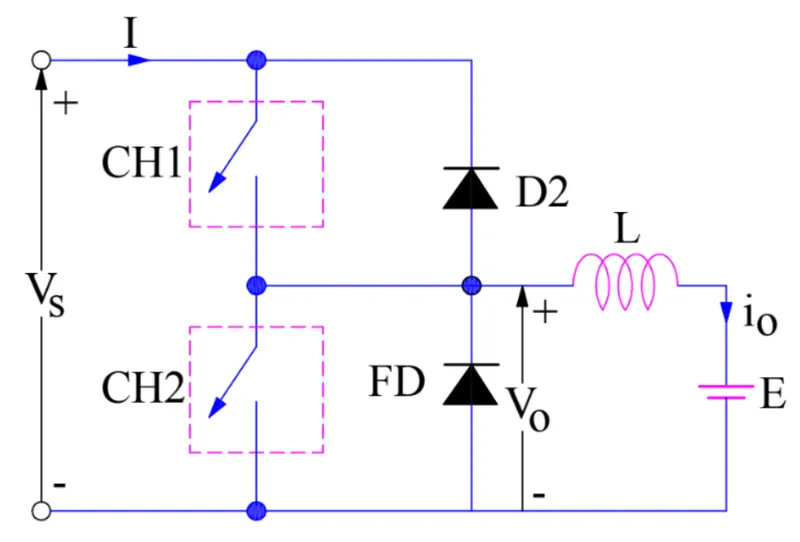
Carefully observe the circuit diagram. You will notice that chopper CH1, free wheeling(FD) and loadare forming Class-A Chopper whereas chopper CH2, D2 and Load are forming Class-B chopper. Both these choppers are connected in parallel. To obtain first quadrant we should switch ON chopper CH1 and for getting second quadrant operation we should switch ON chopper CH2. Let us discuss this in detail.
case1:
When chopper CH1 is switched ON, source Vs directly gets connected to the load and hence, load voltage Vo is equal to source voltage. The direction of load current is from source to load as shown in the circuit diagram which is assumed positive.
When CH1 is switched OFF, the free-wheeling diode FD comes into the circuit as it gets forward biased and hence shorts the load. Therefore, the output voltage Vo becomes zero. However, the io continues to die down through the FD and L in the same direction as shown in circuit diagram. Thus, the average output voltage Vo and current Io are positive and hence operation of chopper is in first quadrant. In fact, this is the Class-B mode of operation.
case2:
When chopper CH2 is switched ON, load DC source E drives current through CH2 and load. The direction of this current io will be opposite to that shown in circuit diagram and hence is assumed negative. Output voltage Vo is zero during this time. When CH2 is made OFF, diode D2 gets forward biased and hence the current into the source from the load. The output voltage is Vs in this time as the load is connected to the source through D2 during OFF time of chopper CH2. Thus, the load current is always negative i.e. operation of chopper is within second quadrant. In fact, this is the Class-B mode of operation.
simulink block diagram:
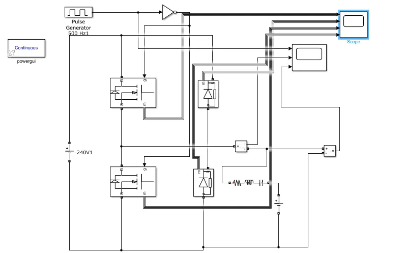
simulink blocks used:
1. MOSFET switches along with diodes
2. RLC series circuit
3.powergui
4. current and voltage mesurement blocks
5. dc voltage blocks and also scope
working:
1. MOSEFET switches along with a diode are connected parallel to each other as two sets as shown
2.a dc voltage source of 24 voltage is supplied to chopper 1 negative teminal is conneted to chopper 2 in order to close the circuit
3. using a pulse generator generate a pulse which passes through not gate in to chopper 1 and chopper 2
4. connect a current measuring block to the chopper 1 and chopper 2 circuits now connect the voltage measuring block to current measuring block as shown
5. connect a RLC circuit and dc voltage source as shown and generate the pulse and then run the model
output:
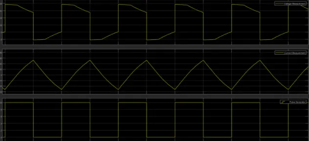
from the above results we get a flucuating current source between positive and negative cycles where as voltage is maintained to positive values
3.
aim: to explain in a brief about operation of BLDC motor.
explaination:
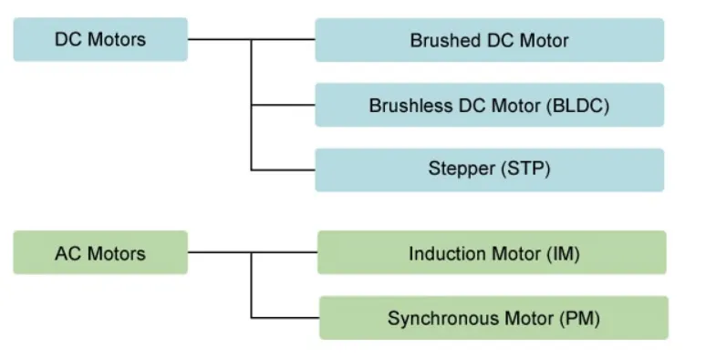
Motors differ according to their power type (AC or DC) and their method for generating rotation (Figure 2). Below, we look briefly at the features and uses of each type.
brushless dc motors:

brushless DC motors do not use brushes. With brushed motors, the brushes deliver current through the commutator into the coils on the rotor. So how does a brushless motor pass current to the rotor coils? It doesn’t—because the coils are not located on the rotor. Instead, the rotor is a permanent magnet; the coils do not rotate, but are instead fixed in place on the stator. Because the coils do not move, there is no need for brushes and a commutator.
With the brushed motor, rotation is achieved by controlling the magnetic fields generated by the coils on the rotor, while the magnetic field generated by the stationary magnets remains fixed. To change the rotation speed, you change the voltage for the coils. With a BLDC motor, it is the permanent magnet that rotates; rotation is achieved by changing the direction of the magnetic fields generated by the surrounding stationary coils. To control the rotation, you adjust the magnitude and direction of the current into these coils
components of BLDC motors:
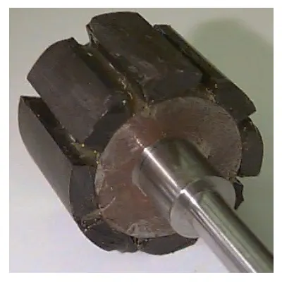
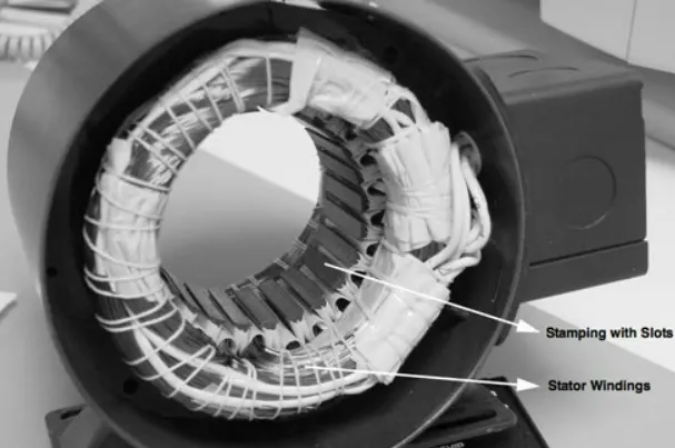
Brushless DC motor has only two basic parts: rotor and the stator. The rotor is the rotating part and has rotor magnets whereas stator is the stationary part and contains stator windings. In BLDC permanent magnets are attached in the rotor and move the electromagnets to the stator.
rotor:
BLDC motor incorporates a permanent magnet in the rotor. The number of poles in the rotor can vary from 2 to 8 pole pairs with alternate south and north poles depending on the application requirement. In order to achieve maximum torque in the motor, the flux density of the material should be high. A proper magnetic material for the rotor is needed to produce required magnetic field density.
stator:
Stator of a BLDC motor made up of stacked steel laminations to carry the windings. These windings are placed in slots which are axially cut along the inner periphery of the stator. These windings can be arranged in either . However, most BLDC motors have three phase star connected stator.
hall sensors:
Hall sensor provides the information to synchronize stator armature excitation with rotor position. Since the commutation of BLDC motor is controlled electronically, the stator windings should be energized in sequence in order to rotate the motor. Before energizing a particular stator winding, acknowledgment of rotor position is necessary. So the Hall Effect sensor embedded in stator senses the rotor position.
types of dc brushless motors:
inner rotor design:
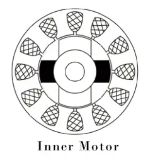
In an inner rotor design, the rotor is located in the centre of the motor and the stator winding surround the rotor. As the rotor is located in the core, rotor magnets do not insulate heat inside and heat get dissipated easily. Due to this reason, inner rotor designed motor produces a large amount of torque and validly used.
outer rotor design:
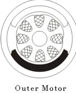
In outer rotor design, the rotor surrounds the winding which is located in the core of the motor. The magnets in the rotor trap the heat of the motor inside and do not allow to dissipate from the motor. Such type of designed motor operates at lower rated current and has low cogging torque.
- Brushless motors are more efficient as its velocity is determined by the frequency at which current is supplied, not the voltage .
- As brushes are absent, the mechanical energy loss due to friction is less which enhanced efficiency.
- BLDC motor can operate at high-speed under any condition.
- There is no sparking and much less noise during operation.
- More electromagnets could be used on the stator for more precise control.