Week-7 Challenge: DC Motor Control
- Run MATLAB demo ‘Speed control of a DC motor using BJT H-bridge’. Modify the model such that armature current doesn’t shoot up when motor changes direction from forward to reverse.
- Refer to help section of ‘The Four-Quadrant Chopper DC Drive (DC7) block’. Compare it with H-bridge model.
- Make a suitable EV model using DC7 block and make result report.
.......................................................................................................................................................
Q1)Run MATLAB demo ‘Speed control of a DC motor using BJT H-bridge’. Modify the model such that armature current doesn’t shoot up when motor changes direction from forward to reverse.
ans -
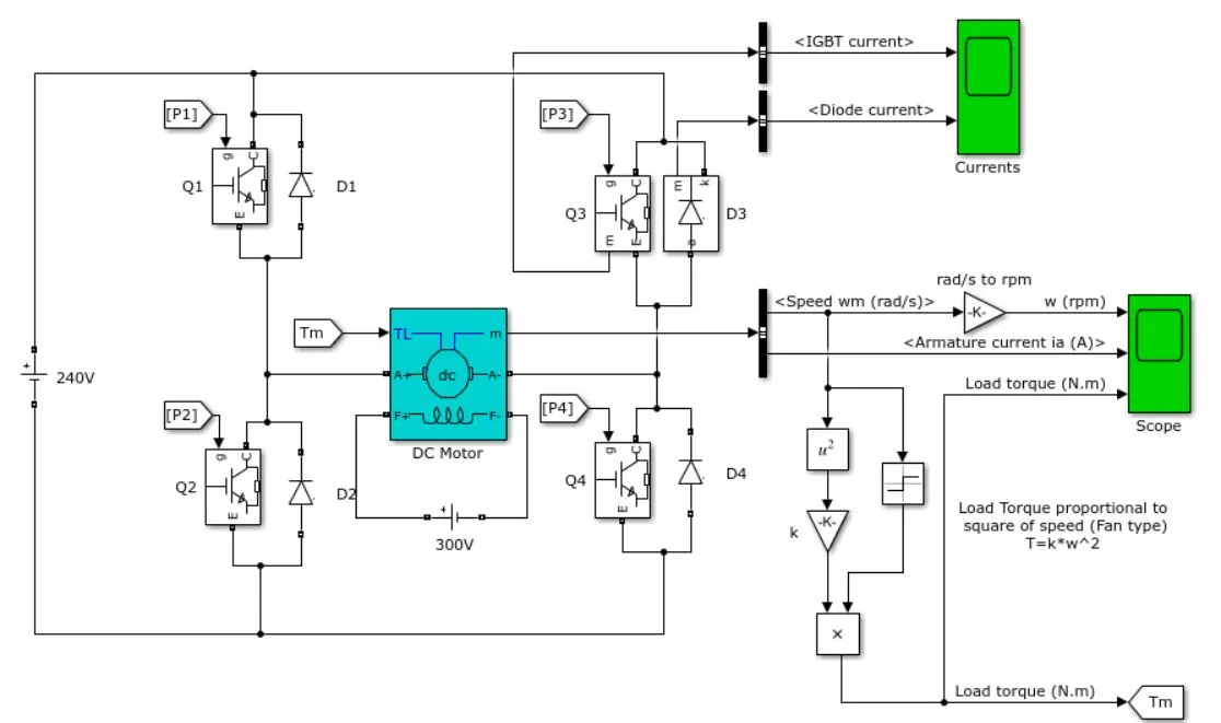
This example shows the simulation of an H-bridge used to generate a chopped voltage and to control the speed of a DC moto
Description
The Bipolar Junction Transistor (BJT) when used for power switching applications, operates as an IGBT. When it is conducting (BJT operating in the saturated region), a forward voltage Vf is developed between collector and emitter (in the range of 1 V). Therefore, the IGBT block can be used to model the BJT device.
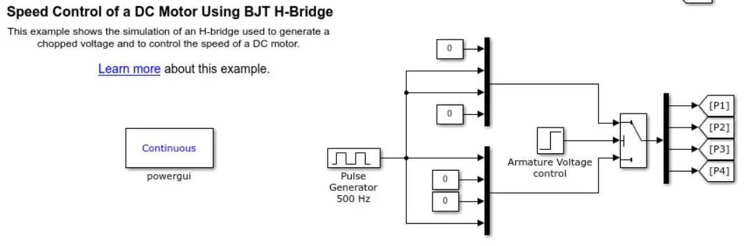
The IGBT block does not simulate the gate current controlling the BJT or IGBT. The switch is controlled by a Simulink® signal (1/0). The DC motor uses the preset model (5 HP 24V 1750 rpm). It simulates a fan type load (where Load torque is proportional to square of speed). The armature mean voltage can be varied from 0 to 240 V when the duty cycle (specified in the Pulse Generator block) is varied from 0 to 100%.
The H-bridge consists of four BJT/Diode pairs (BJT simulated by IGBT models). Two transistors are switched simultaneously: Q1 and Q4 or Q2 and Q3. When Q1 and Q4 are fired, a positive voltage is applied to the motor and diodes D2-D3 operate as free-wheeling diodes
The diodes D2 to D3 provide a safer path for the back emf from the motor to dissipate and thus it protects the corresponding bipolar transistors from damage.
when Q1 and Q4 are switched off. When Q2 and Q3 are fired, a negative voltage is applied to the motor and diodes D1-D4 operate as free-wheeling diodes when Q2 and Q3 are switched off.
Simulation
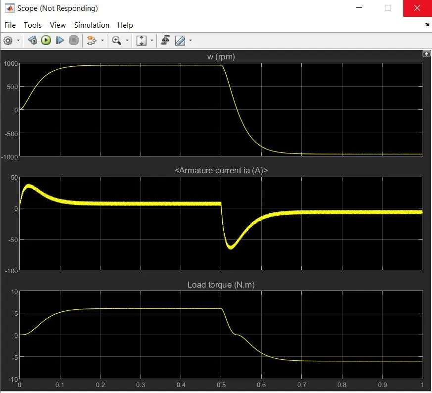
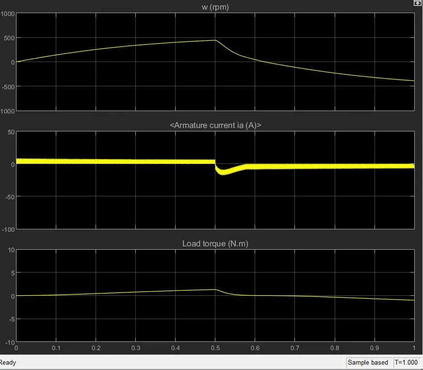
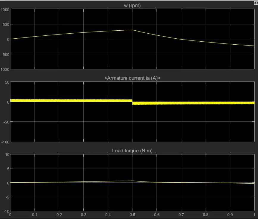
The motor starts in the positive direction with a duty cycle of 75% (mean DC voltage of 180V). At t= 0.5 sec., the armature voltage is suddenly reversed and the motor runs in the negative direction.
'Scope' shows motor speed, armature current and load torque and 'Currents' shows currents flowing in BJT Q3 and diode D3.
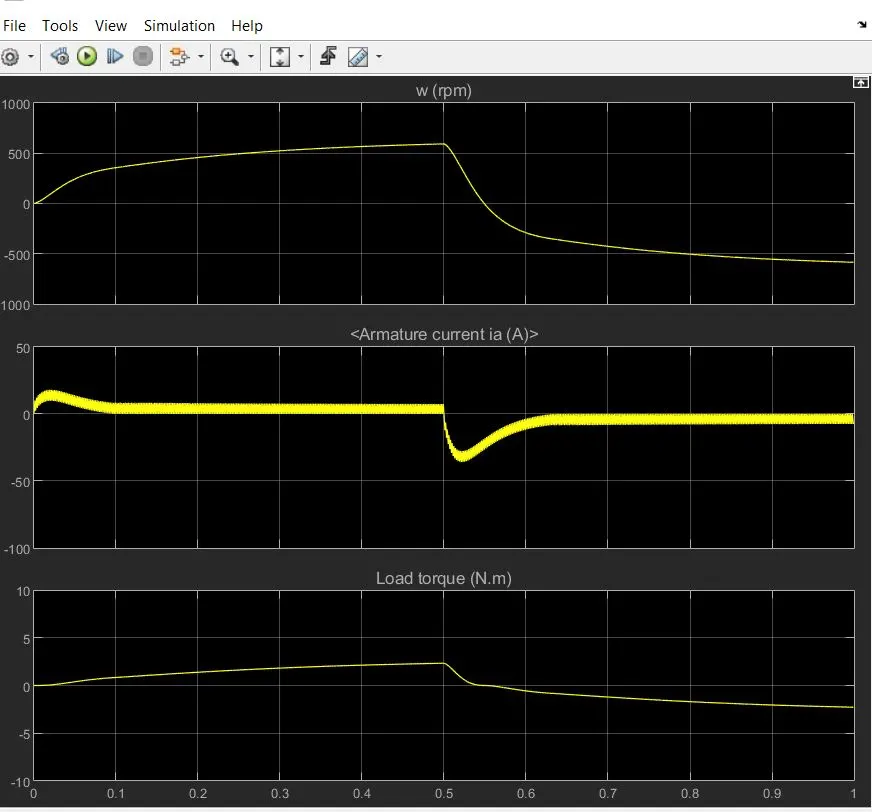
in pulse generator The pulse width allows us to modify the duty cycle of the motor and we can prevent the motor current from shooting up when the motor changes its direction from forward to reverse. By default the duty cycle is 75% and reamining 25% there it is of ..so this kind of switching take place very fast and the control we want it is obtain.
the output of the scope when the simulation is run using the preset values in the pulse generator block. There are
3 output graphs of angular speed, armature current and the load torque all against a time axis.
Description
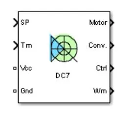
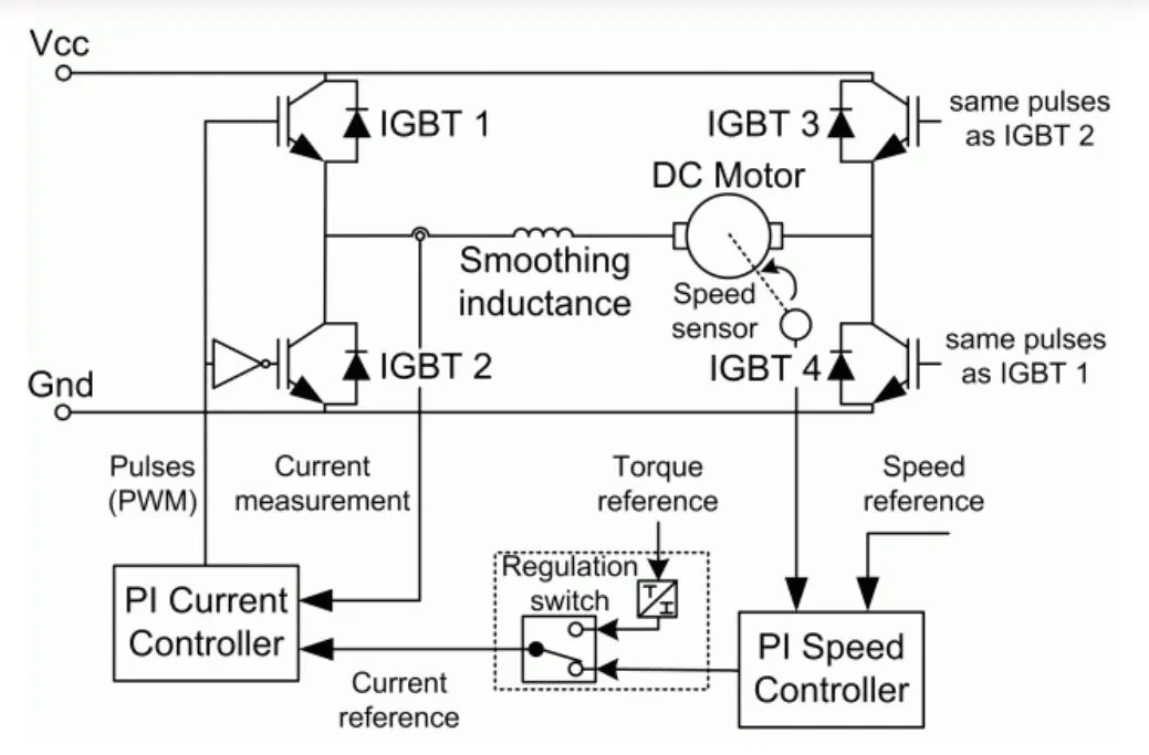
The Four-Quadrant Chopper DC Drive (DC7) block represents a four-quadrant, DC-supplied, chopper (or DC-DC PWM converter) drive for DC motors. This drive features closed-loop speed control with four-quadrant operation. The speed control loop outputs the reference armature current of the machine. Using a PI current controller, the chopper duty cycle corresponding to the commanded armature current is derived. This duty cycle is then compared with a sawtooth carrier signal to obtain the required PWM signals for the chopper.
The main advantage of this drive, compared with other DC drives, is that it can operate in all four quadrants (forward motoring, reverse regeneration, reverse motoring, and forward regeneration).
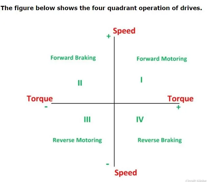
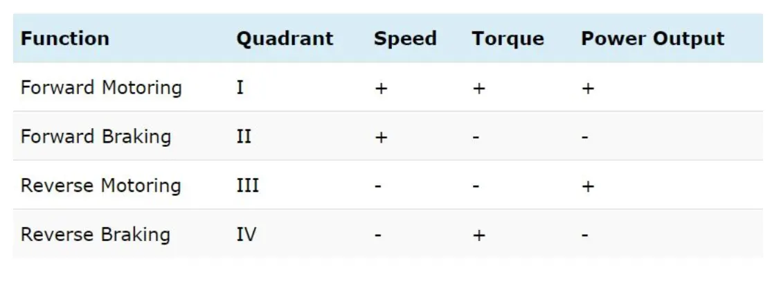
In addition, due to the use of high switching frequency DC-DC converters, a lower armature current ripple (compared with thyristor-based DC drives) is obtained. However, four switching devices are required, which increases thecomplexity of the drive system.
The Four-Quadrant Chopper DC Drive block uses these blocks from the Electric Drives/Fundamental Drive Blocks library:
-
Speed Controller (DC)
-
Regulation Switch
-
Current Controller (DC)
-
Chopper
Remarks
The machine is separately excited with a constant E field voltage source. 1
The armature voltage is provided by an IGBT converter controlled by two Pl
connected in series with the armature circuit.
The model is discrete. Good simulation results have been obtained with a 1—
- The speed controller sampling time
- The current controller sampling time
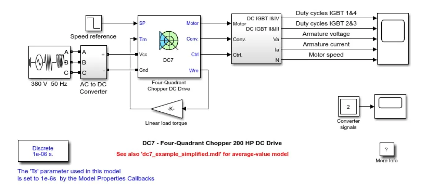
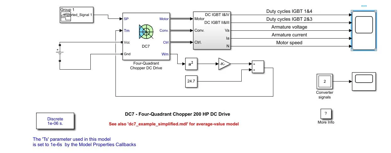
we will replaced the default blocks of the DC7 model with new blocks .
The first block to be replaced is the linear load torque block. with non linear torque equation
For this model of the EV, we will be using a new equation that characterizes the relation between the torque and the speed which is shown below:
Tm : 0.00514ω^2 + 24.7
where:
angular speed of motor (radians per second) ω
Torque of motor in (Nm)
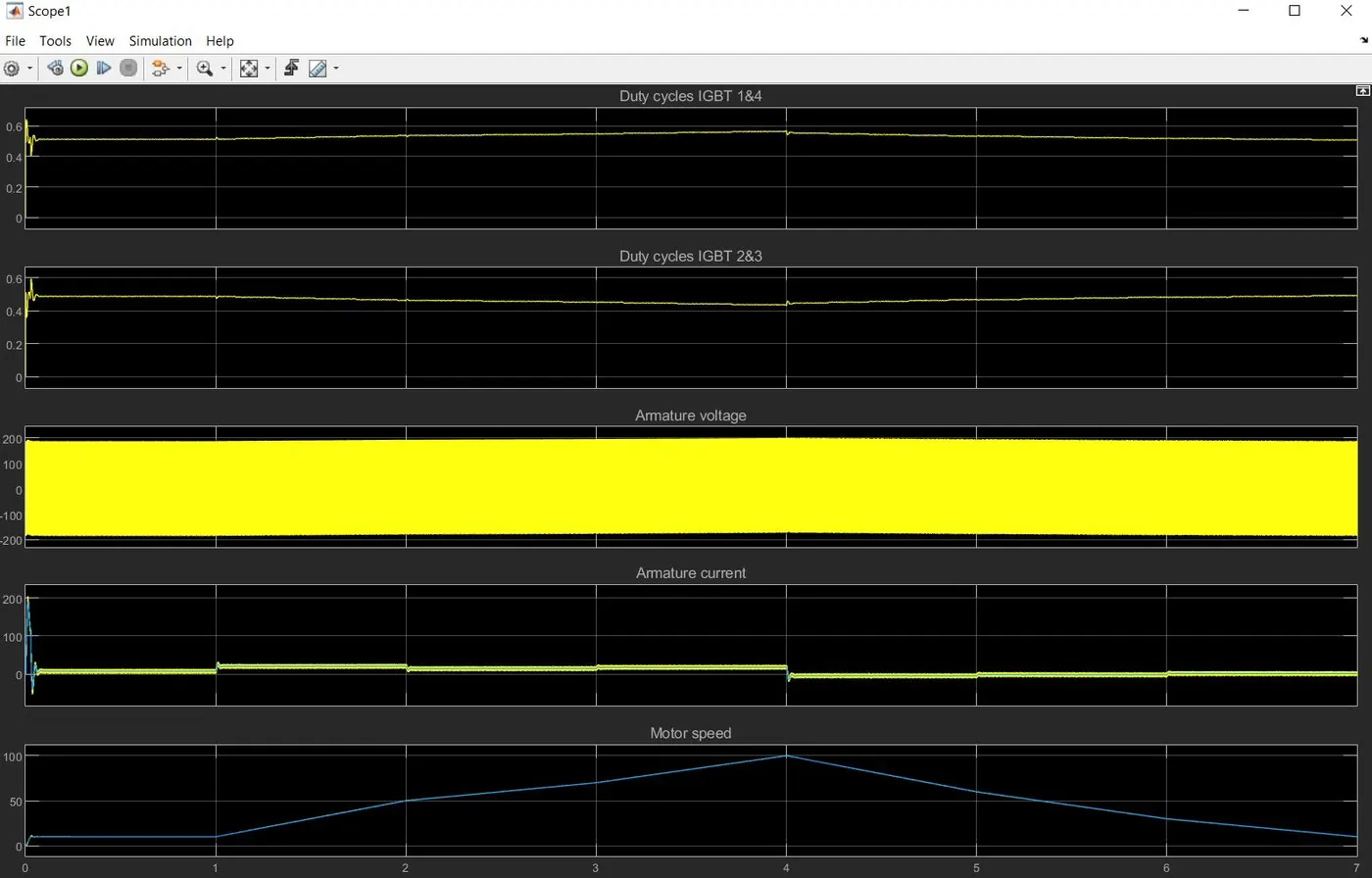
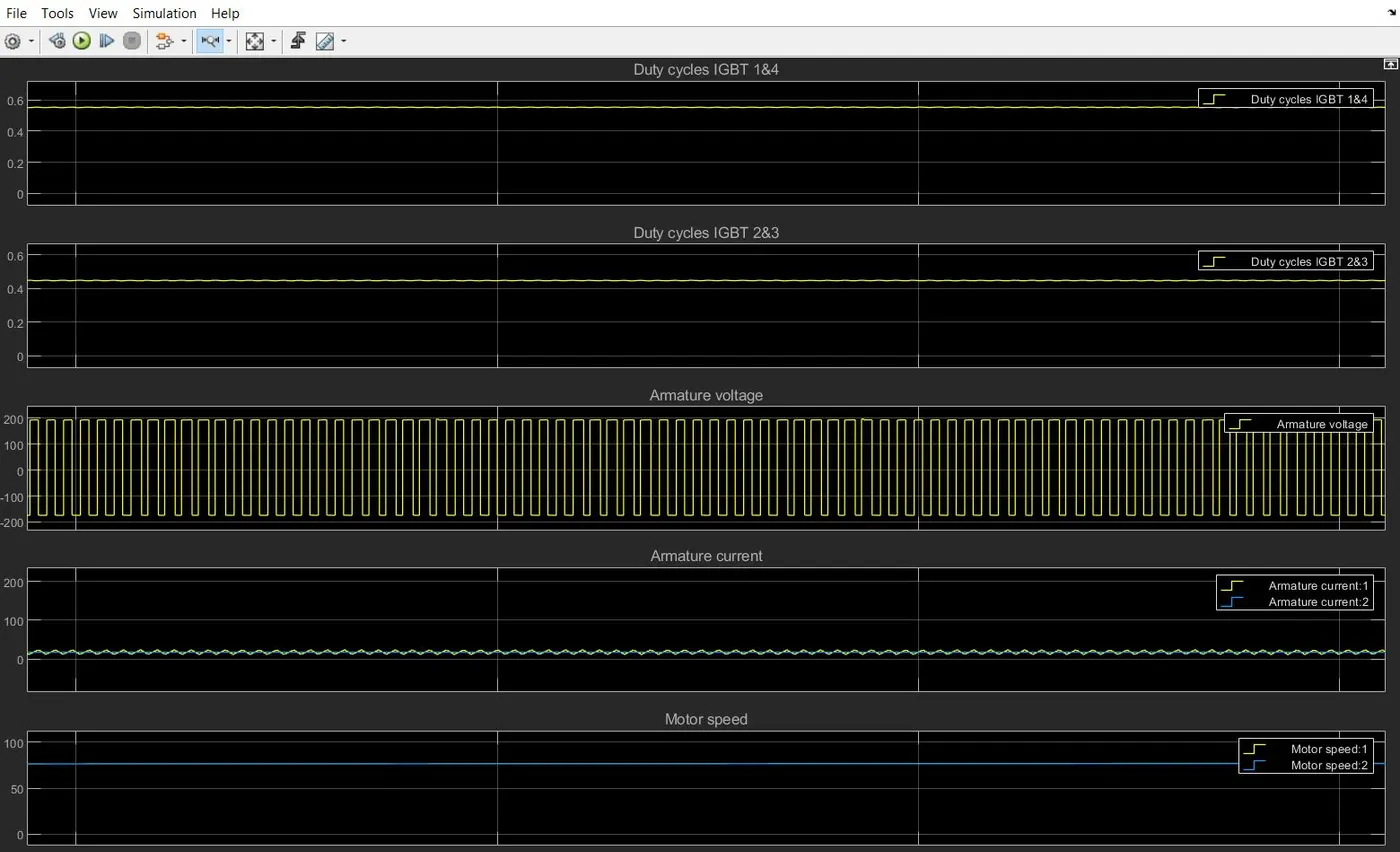
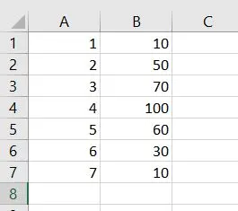
to apply this equation we use blocks Math Function Block,Gain Block, Constant Block ,Add Block ,DC Voltage Block ,Drive Cycle Block or signal builder block and we import our signal xl file in it file attached .make stop time so that it is same as drive cycle.