Project-1: Powertrain for aircraft in runways
- Search and list out the total weight of various types of aircrafts.
- Is there any difference between ground speed and air speed?
- Why is it not recommended to use aircraft engine power to move it on the ground at Airport?
- How an aircraft is pushed to runway when its ready to take off?
- Learn about take off power, tyre design, rolling resistance, tyre pressure, brake forces when landing.
- With necessary assumptions, calculate the force and power required to push / pull an aircraft by a towing vehicle.
7. Design an electric powertrain with type of motor, it’s power rating, and energy requirement to fulfill aircraft towing application. Estimate the duty cycle range to control the aircraft speed from zero to highest. Make all required assumptions. Prepare a table of assumed parameters. Draw a block diagram of powertrain.
..................................................................................................................................
1 ) Search and list out the total weight of various types of aircrafts
ANS
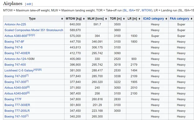
LIST of aircraft with maximum take off weight
c 17 globemaster
maximum gross takeoff weight is 585,000 pounds.
TEJAS
An increase in payload capacity to 6,500 kg (14,300 lb) and internal fuel capacity to 3,300 kg (7,300 lb), will allow it to carry more weapons for longer range.
RAFALE ----take-off weight: 24.5 tonnes.
there are several different weights of the aircraft mentioned (e.g. maximum take-off weight, maximum landing weight, operating empty weight). What do they mean and how they are different?
The different terms represent different weights or masses. For each flight, the weights are taken into account for several reasons.
A brief description about these is below:
Manufacturer's empty weight (MEW)
Also called Manufacturer's Weight Empty (MWE) or Licensed Empty Weight
It is the weight of the aircraft "as built" and includes the weight of the structure, power plant, furnishings, installations, systems and other equipment that are considered an integral part of an aircraft.
This excludes any baggage, passengers, or usable fuel.
Zero-fuel weight (ZFW)
This is the total weight of the airplane and all its contents (including unusable fuel), but excluding the total weight of the usable fuel on board.
As a flight progresses and fuel is consumed, the total weight of the airplane reduces, but the ZFW remains constant.
Maximum zero fuel weight (MZFW) is the maximum weight allowed before usable fuel and other specified usable agents (engine injection fluid, and other consumable propulsion agents) are loaded.
Operating empty weight (OEW) (Roughly equivalent to basic empty weight on light aircraft)
It is the basic weight of an aircraft including the crew, all fluids necessary for operation such as engine oil, engine coolant, water, unusable fuel and all operator items and equipment required for flight but excluding usable fuel and the payload.
It is the carrying capacity of an aircraft. It includes cargo, people, extra fuel. In the case of a commercial airliner, it may refer only to revenue-generating cargo or paying passengers.
Maximum takeoff weight (MTOW)
This is the maximum weight at which the pilot of the aircraft is allowed to attempt to take off.
Regulated takeoff weight (RTOW)
Depending on different factors (e.g. flap setting, altitude, air temperature, length of runway), RTOW or maximum permissible takeoff weight varies for each takeoff. It can never be higher than MTOW..
Maximum landing weight (MLW)
This maximum weight at which an aircraft is permitted to land.
The following image depicts takeoff weight components.
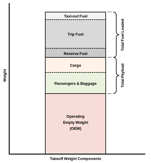
Maximum ramp weight (MRW)
also called maximum taxi weight (MTW)
It is the maximum weight authorized for maneuvering (taxiing or towing) an aircraft on the ground.
It is the total aircraft weight at any moment during the flight or ground operation. This decreases during flight due to fuel and oil consumption.
Read this from left to right, from detailed to generalized. Boxes on the right sum up the separate items which they run across.
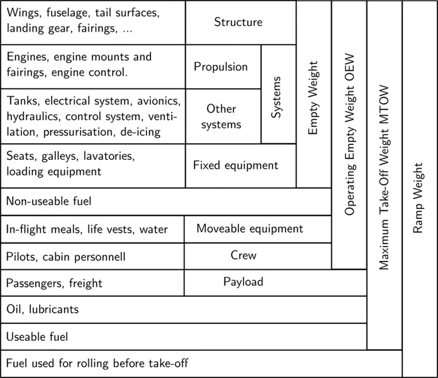
The maximum landing weight is what the manufacturer has certified for landings. Generally, this is MTOW minus some fuel.
Note that every manufacturer has his own standard and might draw the lines between the different weight groups differently. Say, for one the engine quadrant is part of the propulsion system, whereas the other sees it as part of the control system.
Q2) Is there any difference between ground speed and air speed?
ANS –
Relative Velocity:
Two kinds of speed of an airplane: (1) Air speed
(2) Ground speed
AIR Speed : Speed relative to air/wind (measured)……………… Pltot Tube: works on Bernoulli‘s principle mounted in front of aircraft .
Ground speed : Speed relative to ground (Calculated)……
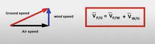
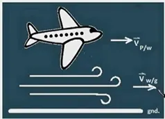
Plane velocity with respect to ground is vector sum of V p/w and V w/g and this two velocity can in any direction eg. in they may be in opposite also
Derivation of this formula
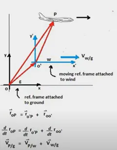
the time derivative of position vector is velocityand thereforewe get this equation vwlocity of plane wrt to ground.
If wind is blowing in the tail direction of the aircraft then, (air speed > ground speed) so,airspeed = ground speed + wind component
If the wind is blowing in the head direction of the aircraft then, (air speed < ground speed)so, airspeed = ground speed - wind component
Let us understand by an example
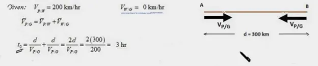
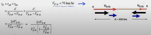
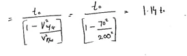
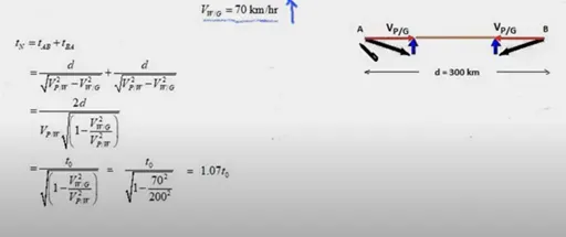
Eg 1} Apilot is supposed to fly due east from Ato B and then back again to A due west. The velocity of the plane in air is 200 Kmph and the velocity of the air with respect to the ground is 70 Kmph. The distance between A and B is 300 Km and the plane's air speed is constant.
(a) If the wind velocity is zero (still air), find t0 – the time for the round trip.
(b) Suppose that air velocity is due east; by what factor the time for the round trip increases over to.
(c) Now, suppose that the air velocity is due north;
by what factor the time for round trip increases over t0.
And
Finding round trip time under different velocities.
A ) wind velocity is zero ,therefor plane air speed and ground speed will be the same
B )
C )
Q ) Why is it not recommended to use aircraft engine power to move it on the ground at Airport?
Ans –
You may have heard the term “pushback” used in the world of aviation but what does it mean? We explain all…
Pushback is an airport procedure that results in an aircraft being pushed backwards away from an airport gate by external power, which is usually provided by pushback tractors or aviation tugs.
You may consider it strange that external power is used in order to push an aircraft backwards but, although the majority of aircraft are able to move backwards (known as a powerback) it may lead to avoidable damage being caused, either to the engine, other equipment being used during the procedure, or the terminal building itself. This is why pushback tractors and aircraft tugs are generally preferred to ensure that aircraft is safely moved from the gate.
In regards to tugs, they are hugely capable of moving the majority of aircraft ranging from light, single-engines to business jets, narrow-body airliners and more. Another positive is that aircraft tugs are able to successfully move the majority of aircraft without the need for adapters, although they tend to be required when it comes to moving more unique planes.
More recently, electric tugs have become more commonly used within the aviation industry due them being more environmentally-friendly when compared to gas or diesel alternatives. Another benefit is that electric tugs can also be safely operated inside a closed hanger, which provides them with an increased level of flexibility when compared to gas and diesel tugs.
So, if you hear someone in the industry refer to a “pushback tug“, you will now fully understand what procedure they are referring to. In short, they want a tug to push an aircraft away from an airport gate.
It is true that airplanes do not have a reverse gear, we used to have it in our car, but airplanes can pushback themselves using the thrust reversers.
It is also known as Powerback procedure. This method is used when the pushback tractor is unavailable or is inoperative.
But this powerback system is not used due to the following reasons—
- Need to Conserve Fuel. Using reverse thrust for pushback, consumes a lot of fuel. Aviation fuels are quite expensive. Therefore, it becomes more expensive for the airline itself. Therefore, to cut down expenses and to conserve fuel, airlines discontinued this practice.
- Cause more wear and tear. Since, engines were being used for pushback, other than normal operations, it will cause more wear and tear in the engine parts, thus, reducing the operational life of the engine.
- More Maintainence Costs. Naturally, an engine which will be operated more, will require more maintainence to check the wear and tear on the engine parts. This will add to the maintainence cost for the operating airline. Thus, this practice was discontinued.
- No rear View. Unlike our cars, planes don't have rear view mirrors to look backwards while using powerback method of pushback. This cause serious accidents.
- Injuries to Ground Personnel. The powerful jet blast created during the reverse thrust can throw away the ground personnel to his feet. To avoid such kind of events, the powerback procedure was discontinued.
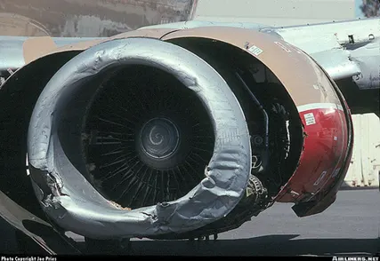
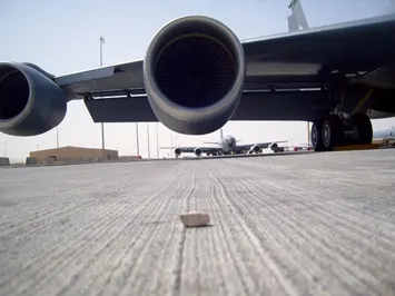
- Damage the Aircraft’s Engine. The powerful jet blast can throw the ground equipments and debris into the engine intake. This will cause a severe damage to the engine and ultimately lead to engine failure.
- Damage the Airport Terminal. The jet blast from the engine’s thrust reversers can throw up anything and hurl it towards the teminal. Thus, it can damage the airport’s terminal.
The biggest issue is the risk of dust and debris from the ground being thrown forward by the reverse thrust and sucked into the engine (known as FOD Foreign Object Debris/Damage). https://www.youtube.com/watch?v=RtUVmntFL80&ab_channel=MelannieHenao
For this reason, very few planes have ever been allowed to power back, all with engines mounted high enough to avoid this risk. On most planes using more then idle reverse below 80knots is considered a FOD risk.

4.How an aircraft is pushed to runway when its ready to take off?
Ans—
Taxiing refers to the movement of an aircraft on the ground, under its own power. The aircraft moves on wheels. An airplane uses taxiways to taxi from one place on an airport to another; for example, when moving from a terminal to the runway.
When aircraft is ready with all the passengers and luggage’s the aviation, pushback is an Airport procedure during which an Aircraft is pushed backwards away from an airport gate by external power.
The aircrafts always moves on the ground following the yellow lines, to avoid any collision with the surrounding buildings, vehicles or other aircrafts.
The taxiing motion has a speed limit. Before making a turn, the pilot reduces the speed further to prevent tire skids. Just like cars, there is a certain list of priorities during taxiing. The aircrafts that are landing or taking off have higher priority. The other aircrafts have to wait for these aircrafts before they start or continue taxiing.
The thrust to propel the aircraft forward comes from its propellers orjet engines. Steering is achieved by turning a nose wheel or tail wheel/rudder; the pilot controlling the direction travelled with their feet. The use of engine thrust near terminals is restricted due to the possibility ofjet blast damage. This is why the aircrafts are pushed back from the buildings by a vehicle before they can start their own engines for taxiing.
Pushbacks are carried out by special, low-profile vehicles called pushback tractors or tugs.
These are heavy weighing low profile vehicles with enourmous torque to do the job of pushing/pulling the large aircraft from the terminals to the runway.
The Tractors are designed with extra weight purposely to offer them enough Traction to push/pull heavy aircraft.
Q ) Learn about take off power, tyre design, rolling resistance, tyre pressure, brake forces when landing.
Ans -
Take Off Performance
Take off performance can be predicted using a simple measure of the acceleration of the aircraft along the runway based on force equilibrium.
The forces involved will be,
T – Thrust of propulsion system pushing aircraft along runway.
D – Aerodynamic Drag of vehicle resisting the aircraft motion.
F – Rolling resistance friction due to the contact of wheels or skids on the ground.
During take-off run the imbalance in these forces will produce an acceleration along the runway.
where dV/dt is the acceleration along the runway and m is the mass of the vehicle.
Rotation Velocity, VR
The procedure for take-off will be that the vehicle will accelerate until it reaches a safe initial flying speed. The pilot can then rotate the vehicle to an attitude to produce climb lift and it will ascend from the ground. The determination of this safe flying speed or rotation speed, VR, is a critical factor in determining take-off performance.
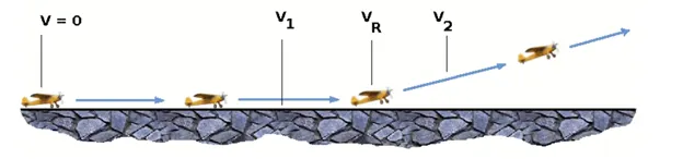
Take-off rules vary slightly depending on the aircraft category. Small commuter aircraft should be considered as meeting FAR 23 rules, transport category aircraft should comply with FAR 25 rules.
V1- Abort decision speed. Below this speed the take-off can be safely aborted. After this there will not be sufficient runway length to allow the aircraft to decelerate to a stop.
V2 – Safe climb speed. V2 must be no less than 1.2 * Vstall. Below this speed aircraft cannot attain sufficient climb rate.
Thrust
The thrust of gas turbine or turbofan engines will be relatively constant during take-off. A good assumption is to use the manufacturer's values for maximum static thrust for take-off calculations.
At V=0 the efficiency is 0 so the above equation makes no sense. At V=VR the efficiency will be in the range 50% to 80% depending on the type of propeller system used and the thrust value at this point will be easy to obtain. In practice, the thrust obtained throughout the take-off roll is roughly constant so this end point value is a good approximation from V=0 to V=VR
Drag
The resistance to motion due to the air viscosity will give a drag Although Drag Coefficient is constant, Drag will increase in proportion to the square of velocity.
Rolling Resistance:
The Rolling resistance force is mainly Experienced by the Tyre when the vehicle moves over any surface.The rolling resistance force is given by the expression,
Frr = urr * (m.g)
Where,
m.g = weight in Newton
urr = coefficient of rolling resistance.
The coefficient of rolling resistance (urr) depends on many factors like the Tyre pressure,Tyre Temperature, Material of the Tyre, Thread pattern of the Tyre and also the Road Roughness and Liquids on the Road. These factors determine the rolling resistance force.
tyre design
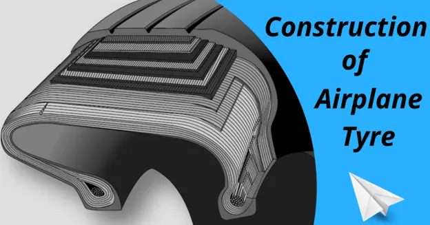
When it comes to safety, tyres are one of the most important components of aircraft. They help to absorb the shock of landing and provide cushioning. It also provides the necessary traction for braking and stopping of an aircraft.
An aircraft tyre is designed to withstand extremely heavy loads while landing, take off, taxing, and parking. The number of wheels required for aircraft increases with the weight of the aircraft, as the weight of the aeroplane needs to be distributed more evenly.
A Boeing 737NG & 737MAX uses 6 wheels, Boeing 787 uses 10 wheels, Boeing 777 uses 14 wheels and Airbus A380 uses 22 wheels. Aircraft tyres work under extreme conditions, carrying up to 340 tons and accelerating at over 250 km/hour at takeoff, in addition to enduring varied environmental stress when in flight and taxiing.
Design and Construction of Aircraft tyre
Carcass plies are used to form the tire. They are sometimes called casing plies. An aircraft tyre is constructed for the purpose it serves.
- They support the weight of an aircraft while it is on the ground.
- It also provides the necessary traction for braking and stopping of an aeroplane.
- Tyre also helps to absorb the shock of landing and provide cushioning the roughness of takeoff, roll-out, and taxi operations.
Unlike an automobile or truck tyre, it does not have to carry a load for a long period of continuous operation. However, an aircraft tyre absorbs the high impact loads of landing, and also it’s operating at high speeds for a short time when required.
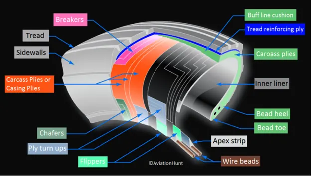
Let’s go through some technical aspects of the tyre.
Retreading – Retreading is methods of restoring a worn tyre by renewing the tread area or by renewing the tread area plus one or both sidewalls. Repairs are included in the tyre retreading process.
Load Rating – Load rating is the maximum permissible load at a specified inflation pressure.
Ply Rating – Ply Rating is used to identify the maximum recommended load rating and inflation pressure for a specified tyre. It is an index of tyre strength.
Speed Rating – The speed rating is the maximum takeoff speed to which the tyre has been tested.
Skid Depth – Skid depth is the distance between the tread surface and the deepest groove as measured in the mould.
Aircraft tyres must have an approved speed and load rating and have sufficient clearance when retracted through landing gear to allow for tyre growth. Tyre growth is the increase in the size of the tyre due to centrifugal forces at high speed.
Aircraft tyres may be Tube-type or Tubeless
Tubeless tyres are more advantageous over tube-type. There is no longer the use of tube-type tyre in recent aviation. Nowadays all airliners are using tubeless tyres. Tubeless that are meant to be used without a tube has the word TUBELESS on the sidewall of the tyre.
Aircraft tyres may be Radial or Bias
Almost all airliners are using Radial tyre. Bias is an older design, and it’s mainly used for road vehicles. Radial tyres have the word RADIAL on the sidewall. Radial tires are more expensive than bias-ply tyres. Radial tires are in demand because of their lower life cycle cost and long term value.
Further Read: Aircraft Radial vs Bias Tyre
Are aviation tyres are conductive?
Yes, Today’s tyres are conductive. Aircraft tyres are manufactured with tread rubber with conducting compounds to permit earthing of static charges.
In early days when tyres were not sufficiently conductive, aircraft used to have a conductive strip hanging down from the axle of the landing gear. Upon landing, this strip would be the first part of the aircraft to touch the earth. This discharges any static electricity accumulated on the outer surfaces of the aircraft. Now you don’t see them anymore.
What is the purpose of Chines in aviation tyre
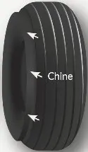
Chines are also called deflectors. Chine tyre used on the nose wheel of aircraft, specially fuselage-mounted jet engines. It diverts runway water away from the engine inlets.
Chines are circumferential protrusions that are moulded into the sidewall of nose tyres that deflect water sideways to help reduce excess water ingestion into the engines. Tyres may have chines on one or both sides, depending on the number of nose tyres on the aircraft.
Aircraft Tyre Standards
Each tyre manufacturer produces their own designs of the tyre with different tread patterns, wear patterns, wear limits etc, and in some cases, different names for the same part of the tyre. But all tyres must meet the approved standards before being accepted by the FAA or CAA.
All commercial aircraft tyres approved under FAA Requirement Technical Standard Order (TSO) C62. A TSO is a minimum performance standard for specified materials, parts, and appliances used on civil aircraft.
Tyre Pressure:
Aircraft tires are usually inflated with nitrogen to minimize expansion and contraction from extreme changes in ambient temperature and pressure experienced during flight
Dry nitrogen expands at the same rate as other dry atmospheric gases (normal air is about 80% nitrogen), but common compressed air sources may contain moisture, which increases the expansion rate with temperature.
The requirement that an inert gas, such as nitrogen, be used instead of air for inflation of tires on certain transport category airplanes was prompted by at least three cases in which the oxygen in air-filled tires combined with volatile gases given off by a severely overheated tire and exploded upon reaching autoignition temperature. The use of an inert gas for tire inflation will eliminate the possibility of a tire explosion.
Aircraft tires generally operate at high pressures, up to 200 psi (14 bar; 1,400 kPa) for airliners, and even higher for business jets.
Brake force when Landing:
Aircraft brakes stop a moving aircraft by converting its kinetic energy to heat energy by means of friction between rotating and stationary discs located in brake assemblies in the wheels.
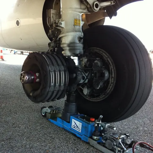
A brake assembly on a Boeing 737NG main landing gear, visible after removal of one the wheels. Source: SKYbrary
Brakes provide this critical stopping function during landings to enable airplanes to stop within the length of the runway.
They also stop aircraft during rejected takeoff events, in which an attempted takeoff is canceled as the airplane is rolling down the runway before it lifts off from the ground due to engine failure, tire blowout, other system failure or direction from air traffic control.
Aircraft brakes work in conjunction with other brake mechanisms such as thrust reversers, air brakes and spoilers. Thrust reversers are surfaces that are deployed into the path of the jet blast from the engines to redirect propulsive thrust in a direction that opposes the motion of the aircraft.
Air brakes and spoilers are flight control surfaces that create additional aerodynamic drag when deployed into the path of air flowing around the aircraft.
Brake design
The primary design considerations for aircraft brakes include the number of discs, the diameter of the discs and the material of the discs.
To illustrate how much energy this is, consider an Airbus A380 — the world’s biggest passenger airplane — performing an RTO at V1. The maximum take-off weight of an A380 is 575,000 kg (1,267,658 lb) and its maximum V1 is around 170 knots (about 195 mph or 87 m/s). A rough estimate for the maximum energy that the A380’s 16 brakes need to dissipate during RTO can be obtained by calculating the kinetic energy of the aircraft (neglecting the effects of thrust reversers, air brakes, tailwinds, headwinds and runway slope).
Since kinetic energy (KE) is a function of mass (m) and velocity (v) according to the equation:
KE = ½mv2
The kinetic energy of the A380 during RTO is calculated as follows:
KE = 0.5 * 575,000 kg * (87.4556 m/s)2 = 2.2 x 10⁹ J = 2.2 GJ
2.2 GJ (gigajoules) is about the amount of energy an average cloud-to-ground lightning strike dissipates. It is also enough energy to power an 8 W LED light bulb (with light output equivalent to a 60 W light bulb) continuously for 8 years and 10 months.
Brake materials
The most common aircraft brake disc material until around 1963 was steel. The introduction of beryllium as a disc material provided improved thermal properties at the cost of material handling difficulties due to the toxic nature of beryllium oxide.
Brake actuator type
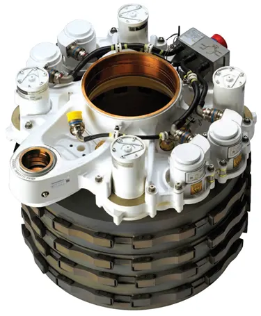
Boeing 787 electric brake.
Source: Safran Landing Systems
(Brake actuators perform the critical task of squeezing discs together to generate the frictional forces that convert the aircraft’s kinetic energy of motion into heat to stop the aircraft. Most brake actuators on commercial aircraft are hydraulic, although electrically powered electromechanical actuators have entered service as well
For a depp insight visit
https://insights.globalspec.com/article/12903/how-do-aircraft-brakes-work
Q ) With necessary assumptions, calculate the force and power required to push / pull an aircraft by a towing vehicle
Ans –
Weight of the Aircraft (Airbus A-380) = 575000kg
Rolling Resistance Coefficient of an aircraft tire(µrr) = 0.004
Wight of the Towing Tractor = 50000kg
Rolling Resistance Coefficient of Towing Vehicle(µrr) = 0.001
Then,
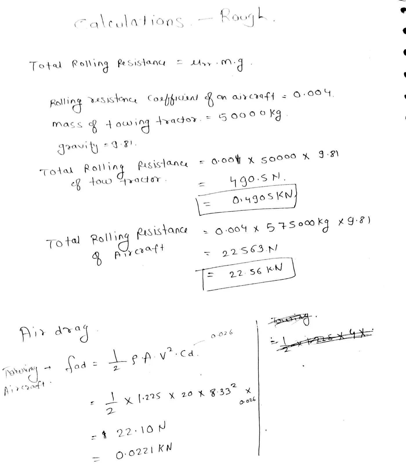
Rolling Resistance Force of Tow Tractor = µrr. m. g = 0.001 x 50000 X 9.81 : 0.49KN
Rolling Resistance Force of aircraft = µrr. m. g = 0.004 X 575000 X 9.81 : 22.56KN
Total Rolling Resistance Force = Rolling Resistance Force of aircraft + Towing Tractor = 0.49 + 22.56
Total Rolling Resistance Force = 23.05KN
Air Drag Force-
The drag force is the force that occures due to the Air Strike effect on the vehicle when it moves. The vehicle moves through a air medium of particular dencsity value with certain speed this causes the air strike against the vehicle body and it causesDrag Force on the vehicle.
The Aerodynamic Drag is given by the following expression-
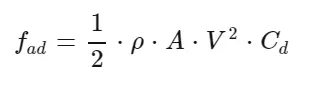
Where,
p = Density of Air Medium
A = Frontal Area Of the Vehicle which strike the Air
V = Velocity with the vehicle moves
Cd = Coefficient of Dragwhich varies different shapes of the frontal area.
Calculation:
Let us assume
The Velocity of the Aircraft while Towing = 30KMPH = 8.33m/s
Density of Air medium(p) =1.225
The Frontal area of the Aircraft = 20m^2
The Coefficient of Drag of the Aircraft = 0.026
Air drag force = 0.5*rho*A*V^2*Cd = 0.022KN
The Air Drag Force of the Aircraft = 0.022KN
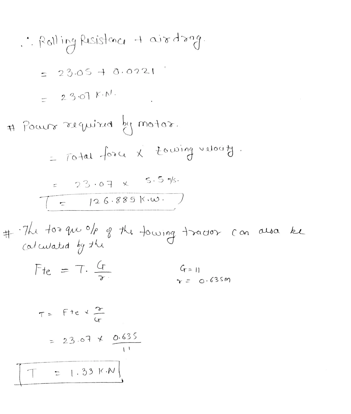
Therefore the total force that the motor needs to overcome = Rolling Resistance of the aircraft + Drad Force Acting on the Aircraft hence the total forces acting = 23.05 + 0.022
The Total Force that the Motor needs to overcome in order to push/pull the Aircraft = 23.07KN
THE POWER REQUIRED-
The power required by the motor is given by the velocity with which the towing operation takes place.
The average speed of push/pull = 20 kmph = 5.5m/s
Power required by the motor = Total Force*Velocity = 23.07*5.5
Power Required by The Motor = 126.8kw
The torque output of the towing tractor can also be calculated by the below steps—
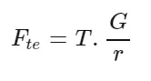
Where,
Fte = The Total Tractive Force(Rolling resistance force + Air drag force)
T = Torque Output
r = Radius of Tire
G = Gear Ratio
For Heavy Duty Towing Tractor we Assume,
G = 11 (for delivering high torque)
r = 25inches = 0.635m
T=Fte*r/G=23000*O.635/11
The Torque required to Push/Pull for the above stated condition = 1.327 KNm
Q ) Design an electric powertrain with type of motor, it’s power rating, and energy requirement to fulfill aircraft towing application. Estimate the duty cycle range to control the aircraft speed from zero to highest. Make all required assumptions. Prepare a table of assumed parameters. Draw a block diagram of powertrain.
Ans –
Ans –
Assumed values same values used in above question
- Weight of the Aircraft -------------------------------------------------575000 kg
- Weight of the Towing Tractor-------------------------------------- 50000 kg
- Rolling resistance coefficient of aircraft------------------------- 0.004
- Rolling resistance coefficient of towing tractor---------------- 0.001
- The velocity of the Aircraft while Towing -----------------------8.33 m/s
- Density of Air medium (rho) ----------------------------------------1.225 Kg/m^3
- The Frontal area of the Aircraft ------------------------------------20 m^2
- The coefficient of Drag of the Aircraft ----------------------------0.026
- Towing tractor Gear ratio "G" (for high Torque output)----- 11
- Towing Tractor tyre radius "r"------------------------------------- 0.635 m
11 . Operational time of the Towing for one cycle -----------------0.33 Hour
- The Battery armature voltage-------------------------------------- 350 V
- The Battery armature current--------------------------------------- 350 A
- The motor terminal voltage for full power output ---------------630 V @ motor terminals
- Power converters used ---------------------------------Bidirectional DC - DC Boost converter
- The maximum duty ratio for achieving full power ---------------------------70%
Assuming the operational time of the Towing truck is around 20 minutes for one cycle
20 minutes = 0.33 Hour
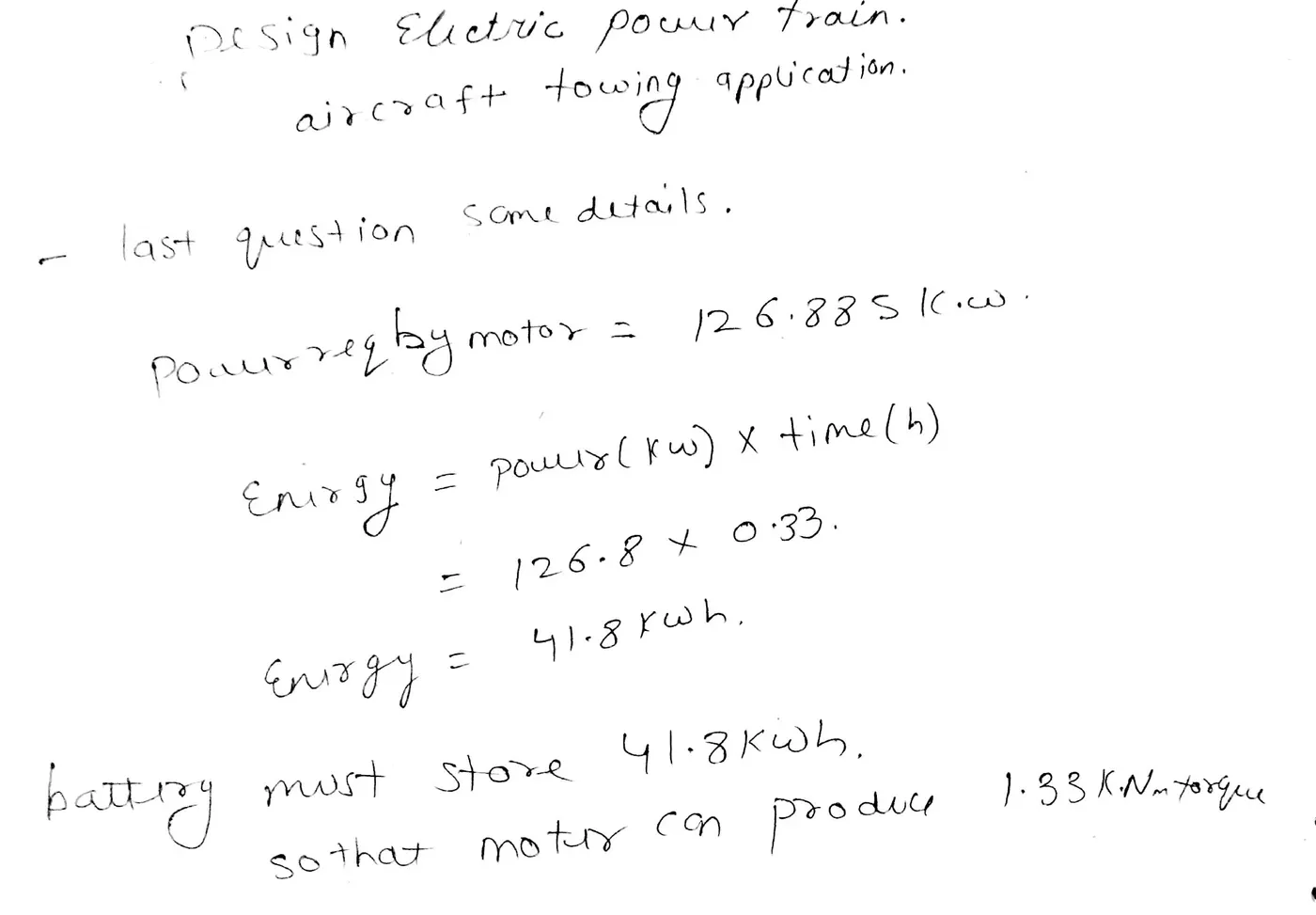
Energy (KWh) = Power (KW) * Time (h) = 126.8 * 0.33
Energy (Kwh) = 41.8 KWh
Therefore the battery must be able to store the energy of 41 .8 KWh and should deliver the energy throughout the run time in order for the motor to produce the 1.32KNm of torque instantaneously.Thus the storage of energy in batteries with high performance ultracapacitors are selected to fulfill the required power delivery.
Motor Selection:
Here we have selected a BrushlessDC Motor type that has a power rating of 126.8 KW and with the gear ratio and the transmission it should be able to deliver 1 .32KN.m of torque instantaneously.
The Battery armature voltage (V) = 350V
The Battery armature current (A) = 350A
For getting the maximum power output from the motor (126.8 KW), the voltage applied to the motor terminals must be 700V (Assume) at the motor's positive and negative terminals.
Power Converters:
Here we use a DC-DC Boost converter to upscale the voltage level from the battery to the required level so that when supplied to the motor we can get the desired power output from the motor.The bidirectional DC—DC converters find applications in places where battery charging, regenerative braking, and backup power are required.The power flow in a bidirectional converter is usually from a low voltage end such as a battery or a supercapacitor to a high voltage side and is referred to as boost operation.During regenerative braking, the power flows back to the low voltage bus to recharge the battery. As a backup power system, the bidirectional DC-DC converter facilitates the safe operation of the vehicle when lCEs or electric drives fail to drive the motor.The boost converter converts the 350V of the armature voltage to a high voltage level of 900 V.
Speed control of the vehicle:
The electric vehicle uses power from the battery source to drive the motor and then further to drive the wheels in order to move the vehicle.The speed and torque generated from the motor is very important to drive the vehicle as per the Driver's desire.lf we connect the battery directly to the motor the motor will spin with a speed and torque characteristics which will be based on the full power of the battery voltage.We does not require full power in all the driving conditions so we need to adopt a power controller between the battery and the motor so that the motor speed may be controlled by the driver to drive the vehicle as desiredFor controlling the vehicle power we use the soft switching operation technique here.The amount of power can be controlled by changing the duty cycle value.Considering the losses we take 70 % of the duty cycle to deliver the maximum power of the motor
Motor terminal voltage = Armature voltage * Duty cycle = 900 * 0.7
With 70% Duty Cycle the Voltage at Motor Terminals = 630 V, Which gives the full power with all the gearings, instantaneously.Thus by varying the Duty Cycle value the speed of the vehicle is controlled.
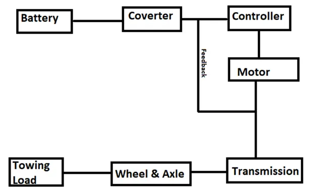
Block Diagram of Powertrain:
Result:
We consider Heavy Aircraft build and so our designed towing tractor is a heavy duty operational vehicle. The power requirements are calculated for the particular load to be pushed/pulled and to achieve this power at the motor output, the motor type and its voltage at the terminals are discussed. Then the power converters are used to upscale the battery armature voltage to the desiered high voltage value so that the motor may spin at full power and requiered torque can be achieved using a Bidirectional DC - DC Converter. Finally the speed control of the vehicle is done with Switching techniques where the duty cycle adjustment can change the motor speed from minimum to maximum.