DC Motor Control Simulation - BJT H-Bridge, 4-Quadrant and 2-Quadrant chopper in Simulink
1. A. Explain a MATLAB demo model named ‘Speed control of a DC motor using BJT H-bridge’.
B. Comment on the armature current shoot-up from the scope results.
C. Refer to the help section of ‘The Four-Quadrant Chopper DC Drive (DC7) block’. Compare it with the H-bridge model.
Solution 1:
Speed control of DC motor using H-Bridge:
Fig: DC motor speed direction concept and H-Bridge control configuration
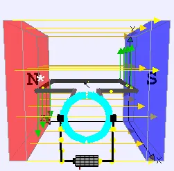
Fig: working of DC motor. Notice the Magnetic field produced by armature coil. If direction of current is reversed then the Magnetic field is also reversed leading to opposite rotation direction
Controlling the direction of rotation
Changing the direction of rotation of a Brushed DC motor is pretty simple. We just have to change the direction of the flow of current in the Armature windings of the Rotor. This can be simply done by chaniging the terminal connevtion to the DC Source.
For example, in the Diagram above when A is connected to +ive terminal B to Ground the motor rotates in one direction , say Anti-clockwise or Positive. While when the connections are reveresed it A to ground and B to +ive the motor roates in the Clockwise direction or Negative, which is opposite to that of before.
H-Bridge configuration: looks like the leter H uses 4 Controllable Switches with the load (DC Motor ) in the middle.
concept : by controlling the which Switch is ON and OFF we can control the direction of current flow in the motor and hence the direction of rotation.
when SW1 and SW4 are closed: the connection is +ive - SW1 -A -B - SW4 - gnd
this is the case as on A to +ive and B to gnd whihch means that the motor rotates in the Positive or Anticlockwise direction.
when SW2 and SW3 are closed: the connection is +ive - SW2 -A -B - SW3 - gnd
this is the case as on B to +ive and A to gnd whihch means that the motor rotates in the Negative or Clockwise direction.
Avoiding Short Circuit: SW1 - SW3 and SW2 - SW4 should not be ON Simultaneously else the Motor will be shorted and can cause hazardous situations.
Controlling the Swithes: As the switched mucst be controllable and they should be able to hanndle large amount of power . Power Seminconductor Switches are used to achieve this control. They can be power BJT, MOSFET,etc
by applying the control signal to the control terminal of the switches we can gain the ability to control the operation of the motor.
Controlling the Speed of rotation
As we know speed of a DC Brushed motor is directly dependent on the applied voltage.
as from the relation:
`omega = V_t/(kphi) - R_atau/(kphi)^2`
by changing `V_t` we can change the `omega`
Changing Applied voltage :
most popular method to chnage the applied voltage is the PWM(Pulse Width Modulation) where by varying the Duty Cycle we can vary the Voltage applied.
Fig: illustration of Duty cycle (50,75 & 25%)
using PWM `=>V_(out) = V_("in")xxD`
Note: these pulse signals are directly applied to the Switches in the H-Bridge , therefore the Voltage acorss the motor appears as `DV_s` . We do not need a chopper circuit to control the output of Voltage source. The signals swithing the Swithes in the H_birdge are the one which have the Duty Cycle input along with the decision of which Switch is ON or OFF depending on the direction of rotation required.
MATLAB demo model named ‘Speed control of a DC motor using BJT H-bridge’
Aim of the Demo: Simulation of H-Bridge to generate a Chopped Voltage and Control Speed of a DC Motor
So we see 2 parts: Generation of chopped voltage: to create a Variable Voltage in order to control the Speed of rotation of DC Motor
And direction of rotaion decided by to which Swithces the Duty cycle signal is applied to.
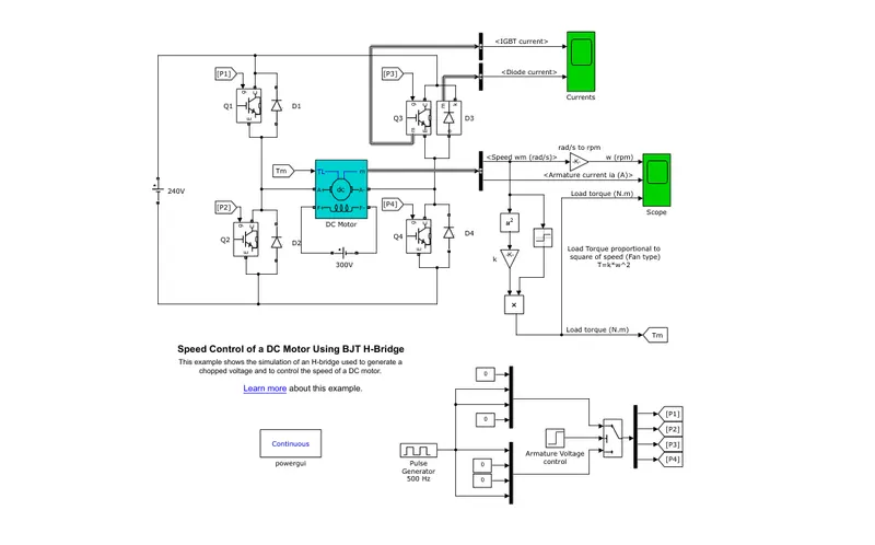
fig: the demo model by MATLAB
Explaination of the Model Working
Components Used in the model:
DC Source: DC source is 'Ideal Voltage DC source' with 240V
DC Motor: 'DC machine block' with wound field type so the connections to the field windings are available to connect it to a source. Here the source is a DC source of Voltage = 300V. Specs: 5HP, 240V ,1750RPM
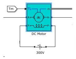
Fig: DC motor used in demo (wound type sperately excited)
Motor Load: the load here used is a Fan load. Whose Torque is proportional to square of Speed. `T_l propto omega^2`
here the load torque is such that: the constant of proportionality is 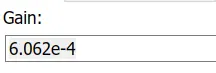
Note: Speed of the Rotor and that of our Fan load will be same since both of them are mechanically coupled together, so to find the load torque we have to use the relation of `T_l propto omega^2` which can be done by taking the speed output of the motor and then squaring it and multiplying it with a proportionality constant.
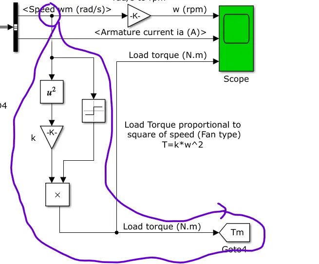
Fig: how `T_l = komega^2` is implemented to get `T_l` k= `6.062xx10^(-4)`
this goes into a goto block which feed this as the `T_l` into the motor as can be seen in the DC motor block
putting a scope we can see that the load torque does follow the square relation as can be seen below. Signum block to apply the right direction of torque wrt to the rotation direction of motor.
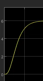
Fig: Torque char of our mechanical load
Switching Device: Although the name of the demo is 'BJT H-bridge' the blocks used are of IGBT this is because when operated in the 'Switching region' (Cut-off and Saturation region rather than the Active region of operation) the BJT performs and has behavior much like that of an IGBT. When conducting in the Saturation region i.e. ON the forward volatge drop is of the order of 1V. So it can be modelled using an IGBT block as the behavior is very close.
there also 'freewheeling diodes' connected in Anti-parallel directions of the switching devices so that when the IGBTs/BJTs are off the current does not stop conducting and the motor keeps on rotating.
the H-Bridge: it is implemented in the same way as explained in the introduction. With the use of 4 BJTs in the H configuration and the motor in between.
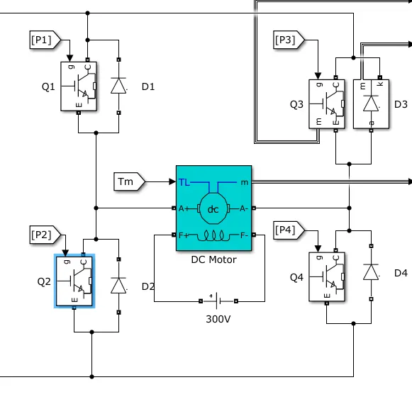
Fig:H-Bridge configuration implemented
Switching Signal applied to the Switches ogf H-Bridge:
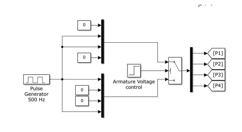
Fig: Signal Input to the switches of the H-Bridge
the pulse applied to the swithes are created with a pulse generator. since there are 4 switches a MUX(Multiplexer) has been used. Since at a time only 2 switches can be ON 2 of the inputs in eaxh MUX is 0.Also the combination of Switches is kept in mind for the MUX signals so that no Short circuit can occur (Q1,Q4 and Q3 and Q2)
A duty cycle of 75% is applied. Frequency is 500Hz and hence the time period is `2xx10^(-3)` sec
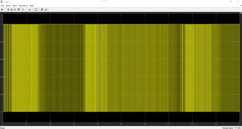
Fig: Pulse genrator signal (500Hz) and duty cycle=75%
Logic for Speed Direction control:
To change the Direction of rotation we have to change the Switches that are turned ON, for that we have to change the Switches that recieve the pulse input as the control signal
this is implemented using a Switch (basic) which uses a threshold of 0.5 and has a Signal input of Step Signal
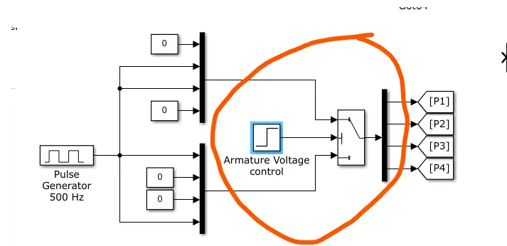
Fig: implementation of Speed Reversal
this switch is named as 'Armature voltage control' this is becaus in Armature v control method of DC Motor Speed control we change the Armature voltage polarity and the direction of roataion changes.
reverse of Speed direction after 0.5 sec
using the Step signal we control the input from the MUX to the H-Bridge Switches, The switch has a threshold of 0.5
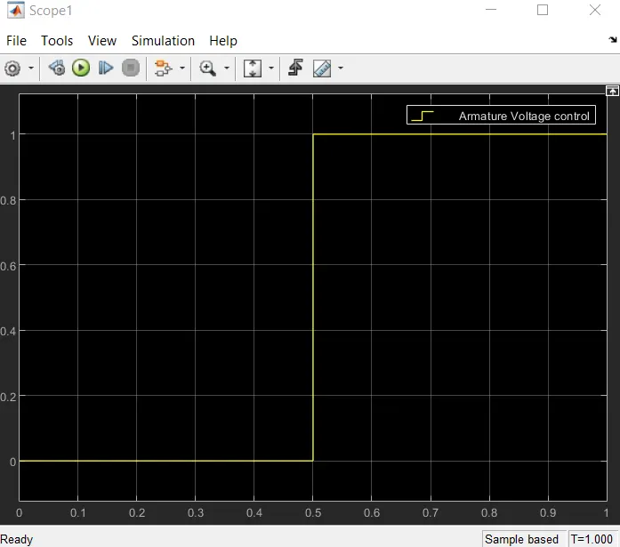
Fig: input to the switch 'Armature Voltage control'
for Forward direction : Q1 and Q4 should be on . which is done for the first 0.5 sec. as The Step Signal is 0 for first 0.5 sec the input 3 goes into the Switches where Q1 and Q4 recieve the Signal while Q2 and Q3 are OFF
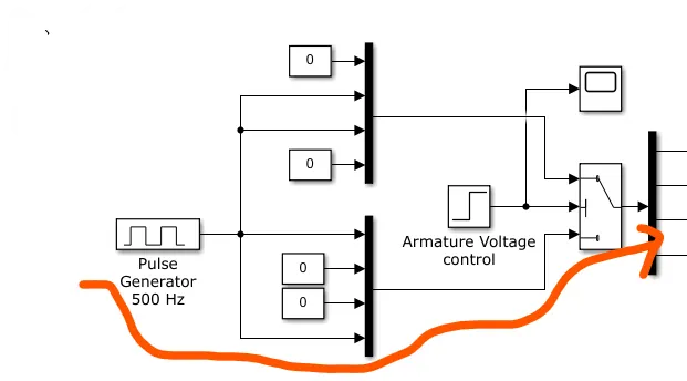
Fig: for first 0.5 sec
so the motor rotates in the positive direction as the current flows like as below in the H-Bridge
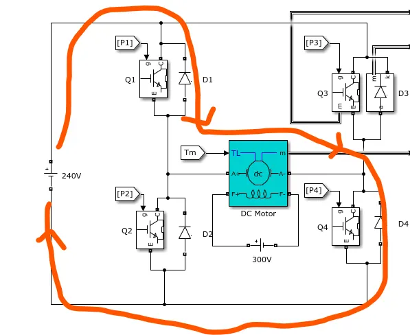
Fig: how current flows in first 0.5 sec
After 0.5 sec:
Signal to switch is equal to 1 and therefore the threshold condition is satisfied
the input 1 goes into the Switches where Q2 and Q3 recieve the Signal while Q1 and Q4 are OFF
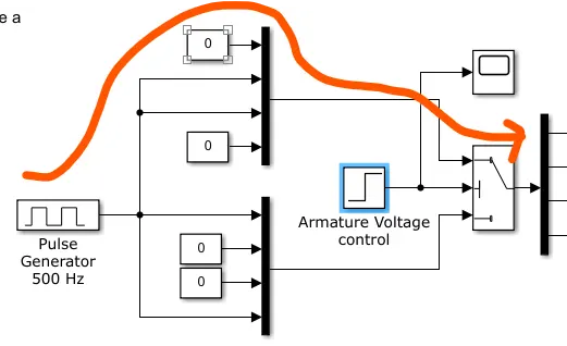
Fig: for next 0.5 sec
so the motor rotates in the negative direction as the current flows like as below in the H-Bridge
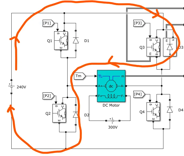
Fig: how current flows in first 0.5 sec
so switch 1 and switch 4 (Q1 and Q4) are on for first 0.5 sec and Q2 and Q3 for next 0.5sec
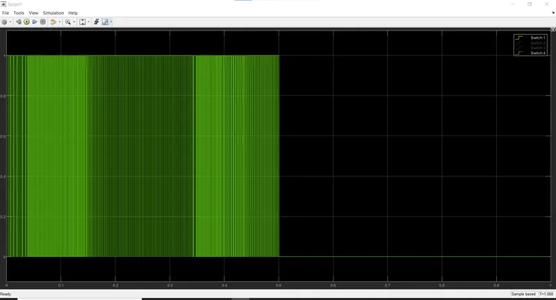
Fig: Q1 and Q4 ON for first 0.5 sec while Q2 and Q3 OFF
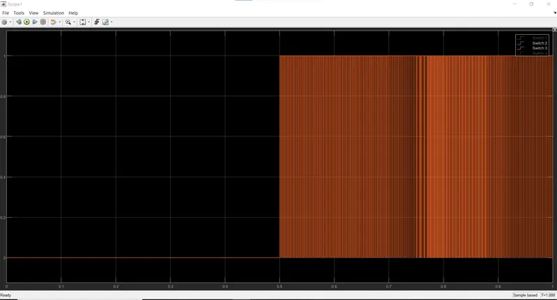
Fig: Q2 and Q3 ON for first 0.5 sec while Q1 and Q4 OFF
Results of Simulation:
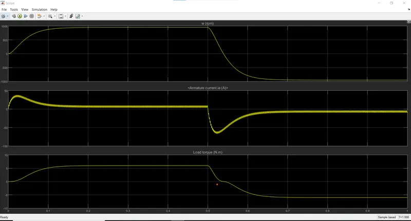
Fig: Result from Motor output (Speed ,Armature current and Torque)
Explaination
i)Speed: as the motor is supplied by the current in a particular direction the speed of the motor increases and keeps on increasing until it motor torque becomes equal to that of the load torque after which the Steady State speed is achieved.
ii)Armature Current:
B. Comment on the armature current shoot-up from the scope results.
when the Motor rotates in a particular direction a 'Back EMF ' is generated .
back EMF is such that `E_b propto omega`
so in the starting the speed of motor is less and therefore the `E_b` is also low
as `=>I_a = (V_t - E_b)/R_a`
at start `E_b` is low so the Armature current `I_a` is high. as the speed increases gradually the back EMF increaes and therfore `V_t - E_b` decreases, so the current also decrease gradually.
iii)Load Torque: as from the relation `T_l propto omega^2` it follows a paraboilic form and then becomes constant after some time, whihc is around the time speed becomes constant, steady state. As `=> T_l propto omega^2` and `=>omega = "constant"` the `=> tau = "constant"`
Result from currents in Q3 and D3
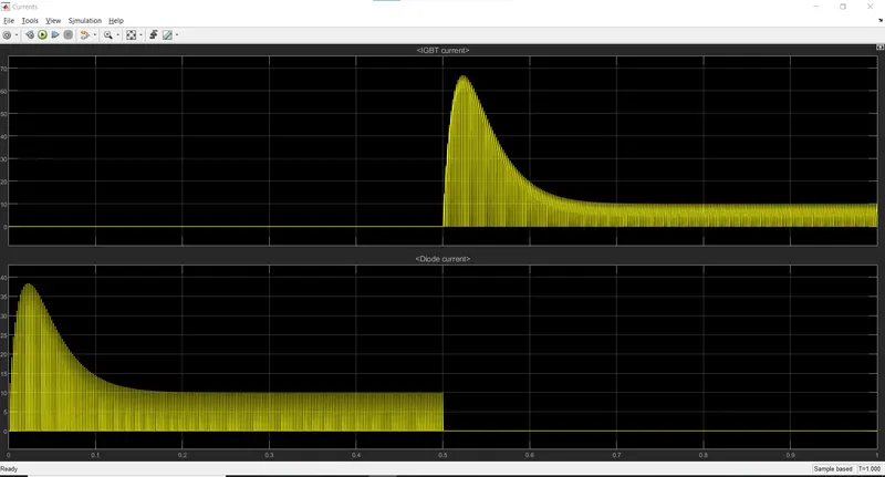
Fig: currents in Q3 and D3 for simulation
BJT Q3
since during first 0.5 sec Q1 and Q4 conduct there is no current through the Q3. While in the next 0.5 sec Q3 and Q2 conduct, therefore now the Q3 conducts the Armature current. (matches the current waveform in our armature current plot)
Diode D3
as for thre first 0.5 sec the motor is forward rotating, Q1 and Q4 are ON so the Diode D3 for freewheeling action cponducts the Armature current. and is OFF during the next 0.5 sec as now the Q3 and Q4 are conductiing
C. Refer to the help section of ‘The Four-Quadrant Chopper DC Drive (DC7) block’. Compare it with the H-bridge model.
Four Quadrant operation of DC Machine:
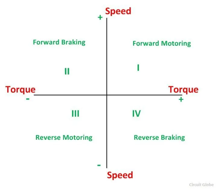
Fig: 4 quadrant operation
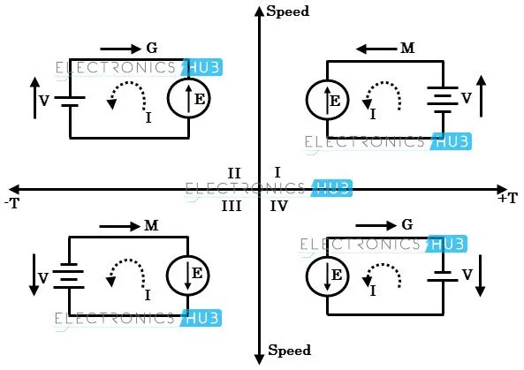
Fig: depicting polarity of Voltage and Direction of Current in each Quadrant operation
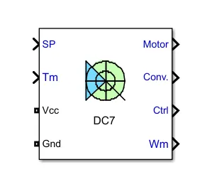
Fig: 4 Quadrant Chopper DC Block
inputs:
SP:speed or torque set point. Can change kargely but will be limited by the acceleration and deceleration change rate ramps
Tm: mehanical Input Load torque
Vcc Gnd: for electrical connection to DC source.Voltage must be adequate acc to the motor
outputs:
Wm: Mechanical Output(Motor speed)
Motor:motor measurement vector (Armature voltage )
and DC voltage measurement Vector(`omega` , `I_a` , `I_f` , `T_e`)
Conv: IGBT/Diode device measurement vector - converter output voltage
Ctrl: control measurement vector (`I_a` reference, duty cycle, speed or torque error, speed reference ramp)
the 4 Quadrant DC Chopper block is a built in block whihc represents a 4-Quadrant DC supplied Chopper for DC Drive Application. It has Closed loop Speed control
Speed control Mechanism: the speed control loop outputs the reference Armature current of thre machine. From this Armature current the duty cycle required is derived using a PI controller It is then used to derive the required PWM signal
Self commutating devices (MOSFET,IGBT,GTO) are used over SCR as it does not require any extra commutation circuit.ALso it has the advantage of Higher frequency which give a more smoother operation of the Motor(less current ripple and hnce less torque ripple).
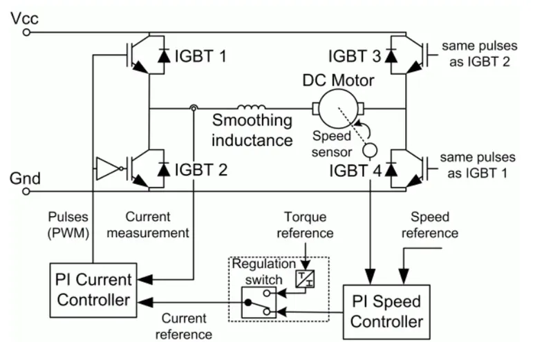
Fig: Blocks used to implement the DC7 block
Looking at the schematic of a 4-Quadrant DC Chopper
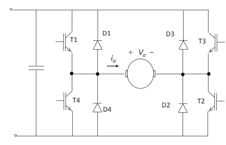
Fig: DC-DC 4 quadrant chopper
Note that it looks very similar to the H-Bridge configuration has 4 switches (controlled) configuration looks like an 'H' with the Machine in the centre.
Looking under the mask of the DC7 block to see how it is implemented using other simulink blocks:
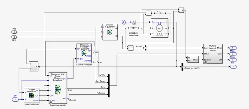
Fig: how DC7 block is implemented in Simulink
it uses certain blocks from the Electric Drive & Fundamental Drive Library
- Speed controller
- Current Controller
- Chopper
- Regulator Switch
- DC Machine
This is a relatively complex block
Speed Controller:
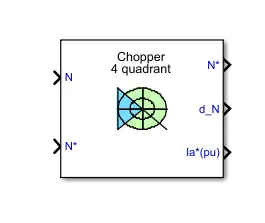
PI speed regulator for a DC machine
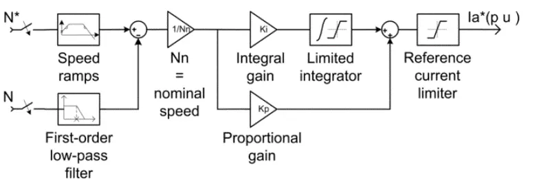
Fig: Implementation of the Speed regulator
it has Rate limiter blocks inside to implement the Speed Acc./Decc change rate ramps to avoid sudden reference changes in the speed which could de-stabilize the system and a Low-pass filter to filter the speed measurement signal.
input: Speed reference and Measured Speed
Output: Reference Armature current which is limited by a Saturation block . This is usually fed to a current controller that will obtain the desired Electromagnetic Torque to reach the desired speed
Regulation Switch
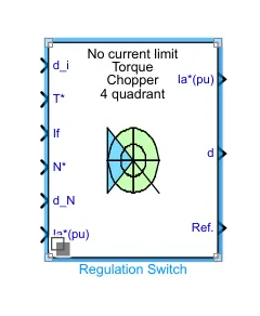
it has 2 parts : DC Machine Torque Controller and Simulink Switch.
switch is used to select the regulation mode(Torque or speed regulation)
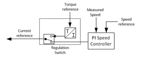
Fig: inside Regulator Switch
torque controller provides reference DC current using `=>I=T/K_t` where `K_t` is motor Torque constant
so now we have 2 current reference 1 from this other from the Speed Controller block.
Depending upon the regulation mode, the switch selects between 2 current references,
input:
d_i: Armature current ref error
T*:Torque reference
If:field current
N*:Speed reference
dN:Speed error
output:
Ia*(pu):Armature cureent refe in per unit
d:Speed or Armature current error
Ref:Speed ref ramp or torque reference
Current Controller:
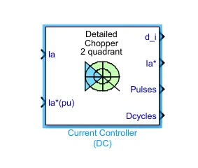
a PI current controller for use with a DC machine . has drive options(DC Chopper drive or Thyristor based DC drive ), options of quadrant(1,2 or 4) and detailed or avergaed value current controller.
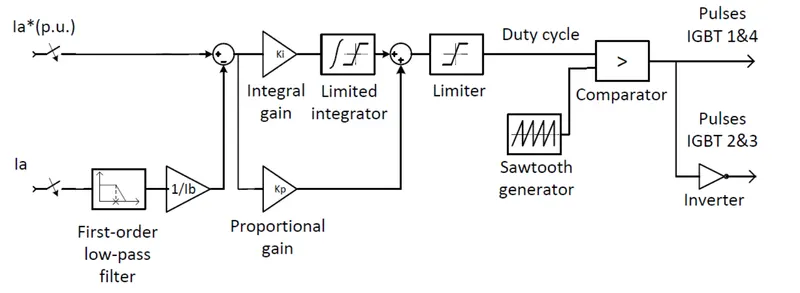
Fig: model of 4 Quadrant DC Chopper current controller
Inputs: current reference from our last block(Regulator switch) and Measured Armature Current from the motor.
Working: it will calculate the Duty Cycle of the chopper using a PI regulator.The duty cycle is compared with a fixed frequency sawtooth carrier signal to obtain the required gate pulses (PWM) for the chopper device. This is illustrated as below.
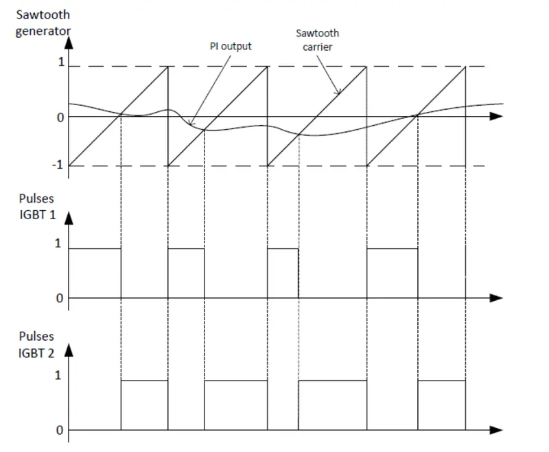
Fig: Comparison of `I_a` from PI with the sawtooth signal to create the PWM signal for the switches
output comes as Pulses and Dcycles for the Switches . Pulses gives the PWM signals required by the switches and Dcycles gives the duty cycles required by them/.
Chopper:
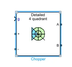
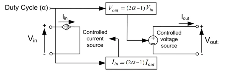
Fig: implementation of Full-Bridge 4 Quadrant DC Drive
Iin = (2α – 1)Iout
Vout = (2α – 1)Vin
with α being the duty cycle value of IGBT 1 and IGBT 4.
Inputs:
g: gate driver input. In 4 quadrant operation it is for IGBT 1&4 and 2&3. Pulses are sent to upper and lower switches of the full bridge converter
+ and -: terminsals for DC source
A and B: output terminals to motor
this is then fed to the DC Motor and the Speed and other outputs are observed.
Comparison with th H-Bridge :
Fig: H-Bridge configuration and $-Quadrant DC Chopper
we can see both are almost same in layout and working. The H-Bridge is actually an Arrangemnt to switch the polarity across a load. the 4-quadrant chopper is actually laid out in the H-Bridge configuartion
Some Similarities are:
| Switches | 4 controllable |
| Configuration | letter 'H' type |
| Supply | DC |
| Quadrant operation | all 4 |
| Control | Speed and Direction |
Difference:
the main difference is that of control type , the Chopper uses Closed loop Speed control using PI controllers for desired speed but the H-Bridge configuration is just a layout to change polarity of voltage and speed can be controlled by changing PWM applied to the switched but there is not closed loop control employed.
---------------------------------------------------------------------------------------------------------------------------------------
2. Develop a 2-quadrant chopper using simulink & explain the working of the same with the relevant results. (Refer to article - Multiquadrant operation of motor )
2 - Quadrant Chopper:
as the name suggests this chopper healps in realisation of the DC machine operation in 2 quadrants. as weknow there are 4 quadrants of operation in a DC Machine (or AC for that matter)
Fig: 4 quadrant operation explained in a Machine
in a 2-Quadrant chopper the 2 quadrants in whihc the machine operates are Quadrant 1(Forward Motoring) and Quadrant 2 (Forward Braking)
from the machine operation we can say that the input side(Voltage and Current) are Current Direction will be Both positive and negative but the Voltage polarity is same.
it is called a Class C Chopper as it is the combination of the working of both Class A & Class B Choppers by operation.
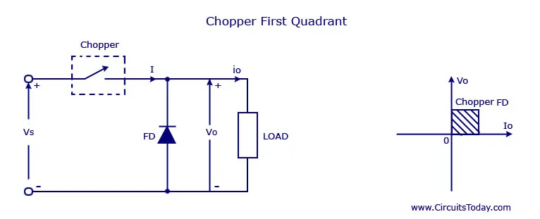
Fig: Class A Chopper (I quadrant operation) `V_o>0 and I_o >0` - Forward Motoring
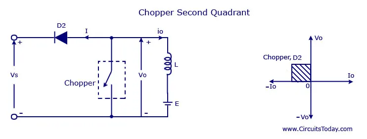
Fig: Class B Chopper (II quadrant operation) `V_o>0 and I_o <0` - Forward Braking
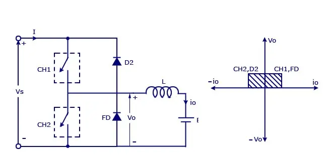
Fig: Class C Chopper (I and II quadrants operation) `V_o>0 and I_o <0 and I_o>0` - Forward Motoring & Braking both
so it behaves both as a Type A and Type B chopper depending upon the I direction.
Behavior as a Type A:
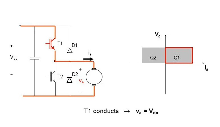
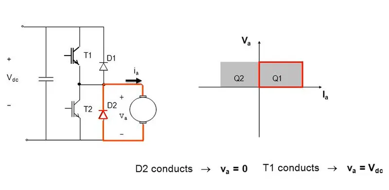
Fig: quadrant I operation of the 2 Quadrant chopper when T1 & D1 conduct
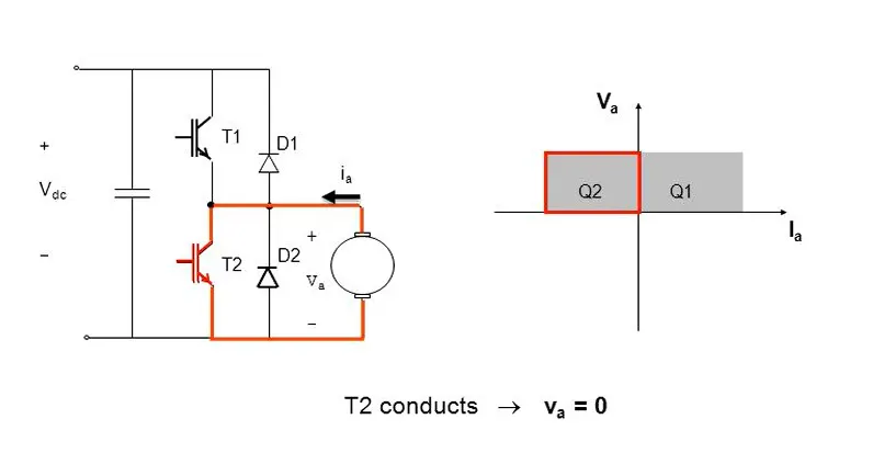
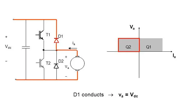
Fig: quadrant II operation of the 2 Quadrant chopper when T2 & D2 conduct
note : in Quadrant I operation `I_o>0` for this to happen we have to make sure that `V_t>E_b`
in Quadrant II operation for `I_o<0` we have to make sure that `V_t<E_b`
Implementation in the Simulink:
we will implement the Class C chopper in the Simulink and see the results:
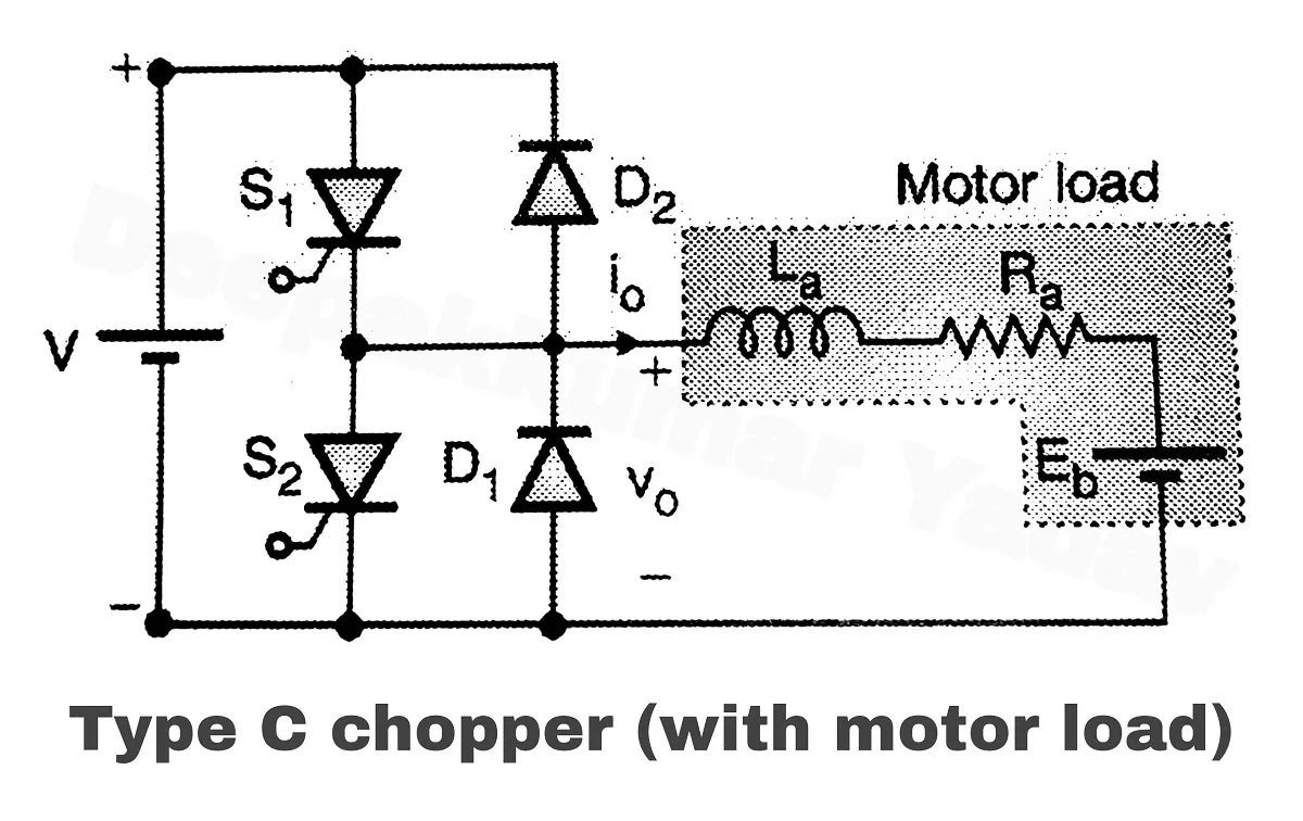
Fig: we will implement this circuit in Simulink with an Actual DC motor
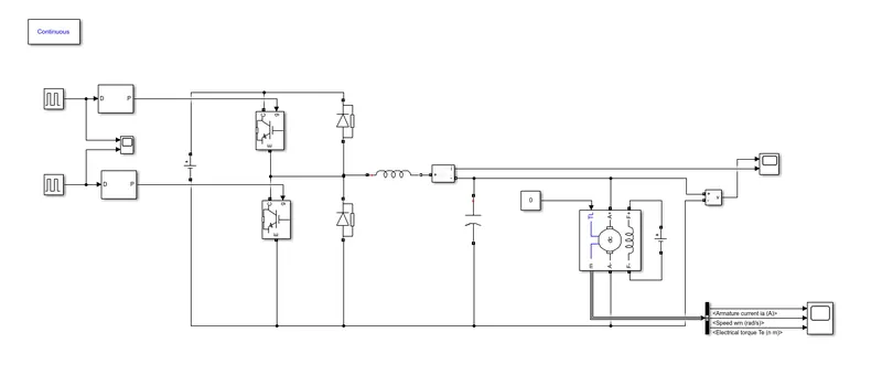
Fig: Simulink implementation of Class 'C' (2-Quadrant) Chopper with a DC Motor
we need 2 controlled and 2 uncontrolled switches for the main chopper circuit
Semiconductor controlled switch use is IGBT and uncontrolled is as usual Diodes ro provide freewhelling action when IGBTs are OFF during the Duty cycle.
DC Machine load: wound type seperately excied DC machine(5 HP, 240V , 1750RPM, `V_f=150V`)
load to DC machine: it is run at no load so `T_l = 0`
inductor in series: Used to reduce the ripple in Armature Current supplied to the motor
Capacitor in Parallel: Used to reduce the Voltage Ripple across the DC Machine load
Creation of Pulses for the 2 IGBTs:
I have used a PWM Generator(DC-DC) block
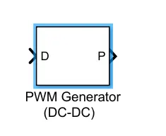
Working: in this block the Duty Cycle input is provided to the PWM generator (Input D)and the Pulses are created accordingly for that duty cycle with the frequency specified in the block. Here frequency used is 5000Hz
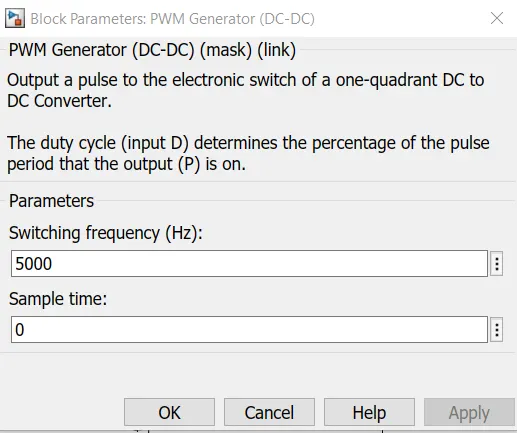
Fig: PWM Generator(DC-DC) parameters . `f_(SW) = 5000"Hz"`
creating the signals:
I have used a Pulse generator as an input to the PWM generator. So when Signal value = 0 , Duty cycle = 0 and there fore PWM has 0 value. When signal value is 0.5, then Duty cycle = 0.5, so a PWM signal is generated by the PWM generator with 50% duty cycle.
to better understand see the example below
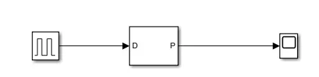
Fig: Pulse Input Given to PWM Generator(DC-DC) . Pulse has : `"Amp" = 0.5 ,"Width" = 20%, "Delay" = 0.1, T = 1"Sec"`
so we should expect a PWM signal such as follows: 0 for when pulse = 0,
Non-zero when pulse is Non-zero [`"width"` (here 0.2 s)] with a `=>"duty cycle" = "Amplitude of the Pulse Generator"` (here 0.5)
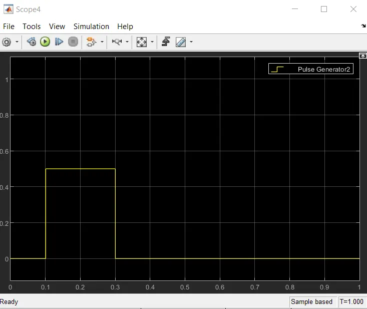
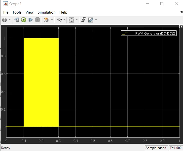
Fig: pulse Input(left), PWM Output(right) with `f_(SW) = 5000Hz`
Also, for Machine to work in braking mode, it has to be first been working in motoring mode so that the enrrgy is stored in the Inductance of the Armature winding. Only then will it act as a Generator by relaeasing back the stored energy in the Inductance and Capacitance back to the Supply when supply is turned OFF. In other words motor has to be in a rotating motion before it can generate the Electrical energy by converting the existing Kinetic Energy by virtue of its motion.
So we have to first turn ON T1 (IGBT 1) to run motor in Forward Motoring and then turn ON T2(IGBT 2) to run in Forward Braking mode.
this is realised by first Switching on IGBT 1 for t=0.1 to t=0.3
and Switching on IGBT 2 for t=0.5 to t=0.7
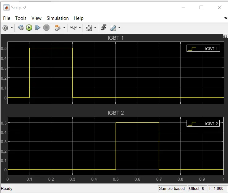
Fig: Swithing of the 2 IGBTs . Controlled by pulse input to the respective PWM Generators of the 2 IGBts
so the input PWM signals to the swithces are:
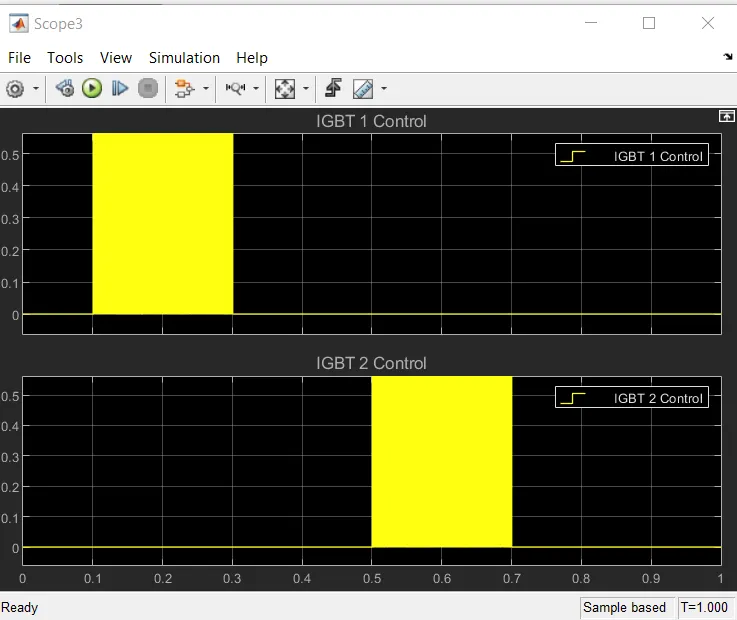
Fig: Control PWM signals to IGBT1 and IGBT2 respectively
Expectation:
So caccording to the theroy when IGBT1 is ON Machine should be in Forward Motoring and when IGBT 2 is ON machine should be in Forward Generating.
So we expect:
- Forward Motoring from t = 0.1 to t =0.3 sec. `tau>0 and omega>0`
- Forward Generating from t = 0.5 to t = 0.7 sec `tau<0 and omega>0`
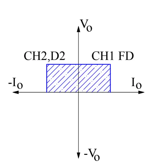
Fig: Forward motoring and Forward Generating in terms of V and I
so expectation in terms of Voltage and Current Measurement from the motor:
- for t = 0.1 to t = 0.3sec , Forward motoring `=> V>0 and I>0`
- for t = 0.5 to t = 0.7sec , Reverse motoring `=> V>0 and I<0`
Result of simualtion:
Fig: IGBTs Position Added for reference while analysing result of Simulation
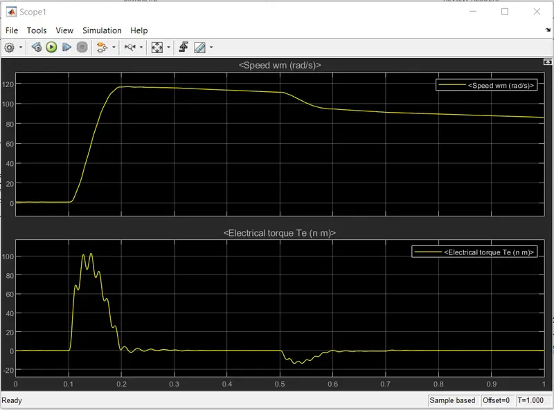
Fig: Result in form of Torque and Speed of the machine (Mechanical)
Analysis:
for t =0 to t = 0.1
no Sw ON so no I or V
For t = 0.1 to t= 0.3
IGBT1 ON , so should be in Forward Motoring by definition. that is , `omega>0 and tau>0`
as we see in the plot `omega>0 and tau>0` for the specified time
for t = 0.3 to t =0.5
no SW is ON so due to external resistances and friction `T_l!=0` but since no supply `T_m = 0` Therefore `=>T_m-T_l<0`
and therfore motro decelerates and speed is decreased. While Torque relatively remains same.
for t = 0.5 to t = 0.7
IGBT 2 is ON so should be in Forward Generation by definition, that is `omega>0 and tau<0`
as we see in the plot `omega >0 "but" tau<o`(notice the bump in the negative direction from [0.5,0.7])
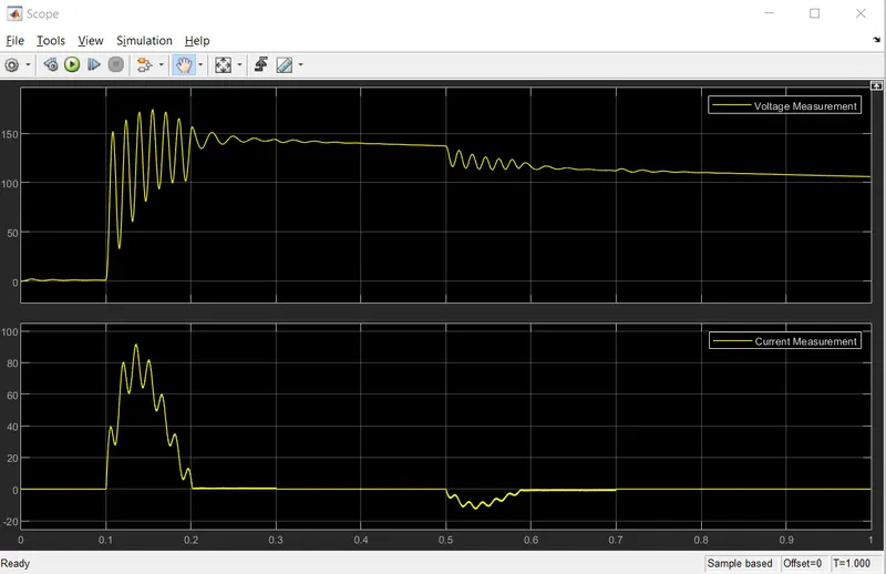
Fig: result in the form of Voltage and Curreent from the motor (Electrical)
Analysis:
for t =0 to t = 0.1
no Sw ON so no I or V
For t = 0.1 to t= 0.3
IGBT1 ON , so should be in Forward Motoring by definition. that is , `V>0 and I>0`
as we see in the plot `V>0 and I>0` for the specified time
for t = 0.5 to t = 0.7
IGBT 2 is ON so should be in Forward Generation by definition, that is `V>0 and I<0`
as we see in the plot `V >0 "but" I<o`(notice the bump in the negative direction from [0.5,0.7])
---------------------------------------------------------------------------------------------------------------------------------------
3. Explain in a brief about operation of BLDC motor.
Solution 2:
BLDC Motor(Brushless Direct Current):
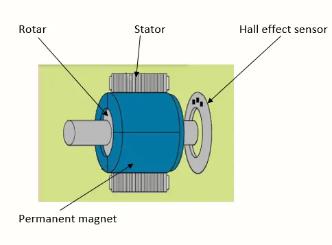
Fig: Illustration of Main components of BLDC motor (Inrunning)
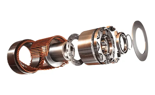
Fig: BLDC motor parts illustrated
BLDC motor from the name we can guess is a DC motor which is 'Brushless' that is it does not employ the use of brushes in commutation as is used in the conventional DC motor. instead of Mechanical Commutaion it employs Electronic commutation.
hence also called as an ECM(Electronically Commutated Motor). Also usually in Consumer Elctronics when the term 'Inverter type' motor is used it is usually BLDC motors.
Naturally therefore it will also not be having the same construction as the Conventional DC Motor as there we needed a commutator since the Armature windings were placed on the Rotor so for continuous electrical contact and reversing the direction of curremt after the rotor has rotated for 180* we needed Brushes and Commutator. This contruction can be seen in the illustration below.
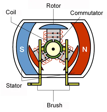
Fig: DC Brushed motor contruction and working
So here the Permanent Magents are placed on the Stator and the Windings on the rotor hence commutation is required for the rerason stated above.
Naturally to eliminate this mechanical commutation the windings should not be placed onto the rotor. Therefore the contruction of Brushless DC motor is different than that if the Brushed DC motor. Here
- the windings are present on the Stator
- the permanent magnets are present on the Rotor
- Now since the windings are on stator they are static and do not need commutation,brushes or connections
Stator / The Armature Windings: consist of `3phi` AC windings distributed in space of the Stator. The changing Excitation in these fields produces a Flux that changes its direction at a speed which depends on the frequency of the current in the excitation.
the excitation waveform could be trapezoidal or Sinusoidal in nature.
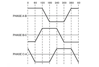
Fig: Trapezoidal waveform to excite the Armature windings in BLDC
Rotor: Unlike DC Brushed machine the rotor does not have any windings, it only consists of pairs of Permanent Magnets . This rotor tries to catch up with the rotating field of the stator making it a 'Synchronous motor'
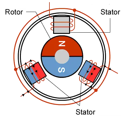
Fig: Contruction and working of BLDC motor(3 coil 2 pole)
Main difference Between BLDC and Brushed Motor: Mechanical commutator in the Brushed Motor is replaced by an Electronic Commutator. RMF and the rotor rotate at the same speed.
Filed inside the BLDC motor is Switched through an amplifier triggered by a commutating device. The controller provides pulses of Current to the motor windings. this controls the speed(`omega`) and torque(`tau`) of the motor. High power Transisitors are used to activate the windings and help in the turning of the motor.
Based on Stator Rotor position:
Outrunner motor:
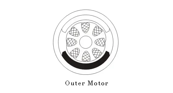
Fig: ourunner motor (Rotor outside, Stator inside)
Filed magnet is a drum rotor which rotates around the Stator.
Since the Permanent magnets of the rotor enclose the Stator windings the heat genrated in the stator windings cannot esacpe the Stator and is trapped. Due to this the Current rating is kept low and hence the torque rating also is low.
Hence have low `tau` and high `omega`
Inrunner Motor
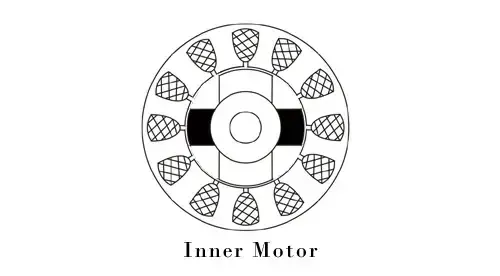
Fig: Inrunner motor(rotor inside the stator)
conventional motor design where the rotor lies on the inside of the Stator . Since the Stator is outside the Armature winding heat can escape easily and hence the heating is less, which in turn means more Current rating ang hence more torque
hence for high `tau` low `omega`
Working Principle:
Similar to the Brushed motor here again it works on the principle of Lorentz Force: when a current carrying conductor is placed in a Magentic Field it experiences a Force on it. And by Newton's Third law the Magnetic field producding element(winding or stator) expereiences an equal and opposite force on it too.
As name of motors as AC or DC depends on the source with which they work . BLDC is a DC motor so it is powered by a DC source but the working and running is not as simple as in a Brushed DC Motor where we just connect the 2 terminals to the terminals of the battery.
here first the DC Supply is convereted into AC Trapezoidal shape(current) through Switching circuits which is then fed to the windings in the Stator.
Feeding windings with the Trapezoidal wave: windings are switched as High and Low signals , which creates a N-pole and S-pole electronmagents respectively.
why rotor rotates: then the Permanent magnets of the rotor try to align themselves with the Stator poles which cause the rotor to rotate. This Stator poles keep on moving as the current waveform keeps on changing hence rotating the rotor.
these pulses of current are provided by the contoller whihc can control the speed and torque of the motor.
Working Explaination
Consider the BLDC motor with 3 windings U,V and W.
Note: controlling the direction and timing of the current into the coils is very important for the BLDC motor to work
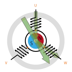
Fig: Excitation in U and W windigs leading to the resultant as seen by the long arrow
so at above instant the U and W windings are excited and the resultant can be seen , the permanent magnets in the rotor will try to align themselves in the direction of the net field. Hence the rotor moves
then in next instant the windingd U and V are excited leading to the resultant into a new direction then the rotor fiuther rotates. And this keeps on rotating.
This can be seen as below
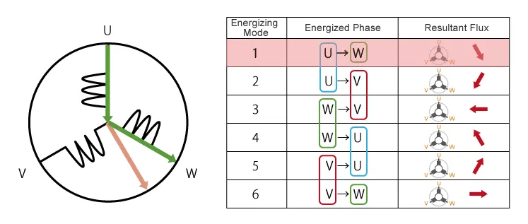
Fig: Illustartion of a 3 winding BLDC and how Excitation of the windings keep on changing the resultant Flux direction
The rotor Permanent magnets try to align themsleves with the rotating flux(orange arrow) of the stator and hence rotor rotates.
we can also use a Sinusoidal Excitation current for a smoother Torque production. As the RMF will be smoother rather than in 6 or multiple steps this reduces the Torque ripple and gives smoother and quieter operation.
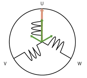
Fig: Sinusoidal Excitation and RMF as a result of it
Inverter control:
see in mode 1 the current moves in the direction U to W and in mode 4 it is W to U. This is Exactly opposite to each other whihc means that we need an Alternating Current since the direction of the curent reverses. This current reversal is done using brushes in Brushed Dc motor but here Inverter ins employed.
And as inverter is used we can control the Amount of voltage employed on the coils as well as the magnitude of the current.
to control Voltage: we can use PWM(Pulse Width Modulation) by adjusting the duty cycle we can gain control. Increasing duty cycle increases V and Decreasing it has the effect of reucing Current.
for 120 degree conduction control we need only 2`phi` voltage control but for sinusoidal contorl 3`phi` Voltage control is required. And the software implementaion is also complicated in Sinusoidal control.
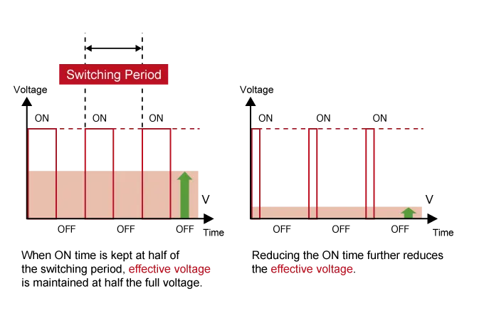
Fig: Effect of PWM duty cycle on Output Voltage
Positional Sensors:
One very important feature in BLDC motors is the use of Positional Sensors to detect the position of the Rotor. This is because motor control must be coordinated with the the position of the rotor, this is very important else the rotor might rotate in the wrong direction. Excitation of the Respective windings as low or high depends on the rotor position because Permanent magnets of the rotor aligh themselves with the RMF
| Sensor Type | Typical Applications | Features |
|---|---|---|
| Hall Element | 120-deg. conducting control | Gets signal every 60 degrees. Relatively inexpensive. Poor tolerance to heat. |
| Optical Encoder | Sine-wave control, vector control | Two types: Incremental (detects displacement from origin) and absolute (detects current position). High resolution. Poor tolerance to dust. |
| Resolver | Sine-wave control, vector control |
High resolution. Sturdy. Can be used in rough environments. |
Fig: Types of Positional Sensors ecmployed in the BLDC with features