Week-6 Challenge: EV Drivetrain
1. Which types of power converter circuits are employed in electric and hybrid electric vehicle?
Solution 1:
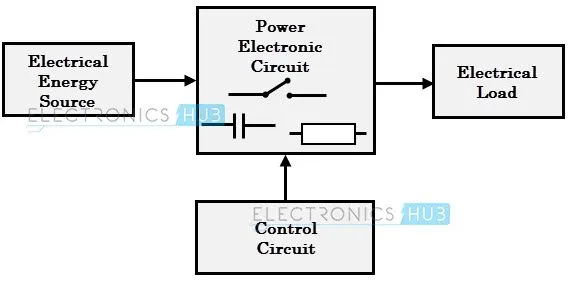
Fig: Simplified Block Diagram of a system with power converter
power converters Are semiconductor devices based circuits which are used to control and condition of electrical power. Note that in any kind of conversion by a power converter `=>"power" = "constant"`
contrary to Signal electronics the Power electronics usually work with higher Voltages,Current and Power level.
Application :
V,F control for speed control of machines: for Synchronous and Induction Machine = variable frequency `=>` variable `N_s` `=>` variable `N_r`
while in case of DC Machines by variable Voltage
many disadvantages are present like no rotaional losses,compact size,closed loop control,(due to the control terminal in the devices used).
they work as Switches by using the Cut-off and Saturation region of the seminconductor devices. Rather than the active region. Also called Switched Mode Power Conversion devices.
Types of power converters employed in Electric and Hybrid Electric Vehicle:
1.Rectifier: AC to DC form conversion of power , power remaining same.
Application in Vehicle: Charging
'phase controlled' if we use a thyristor , we can control the firing angle to get a controlled output. This is mainly employed in the charging of the battery/energy storage of the vehicle . Since the Power System is AC in nature and the battery pack is DC in nature we need to employ this converter to charge the battery pack .
it can be half-wave or full-wave rectifier forr both single and 3-phase electrical power. Where only positive cycle of the AC is used in the former while in the latter both positve and negative cycle is used.
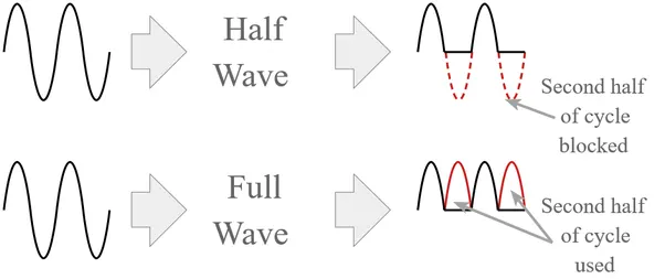
Fig: AC to DC conversion from Half Wave and full wave rectifier depicted
depending upon the load the waveform changes as well as the firing angle of the Contorlled Switch . Both Uncontrolled switches(diode) and controlled swithces can be used(SCR).
when the switch is SCR we have the option to introduce a delay between when the switch is actually Forward biased and when it starts conducting. This is called the Firing angle (`alpha`)
this gives control over the values of Voltage and Current from the Device. For example , for a Half-wave Controlled Rectifier
`=>V_o(avg) = (V_m/(2pi))[1 + cosalpha]` and
`=>I_o(avg) = (V_m/(2piR))[1 + cosalpha]`
so by controlling the firing anlge we can control the output V and I to a certain extent.
2. Inverter: Input is DC power which is converted to AC with Variable V and Variable f
variable frequency is obtained by controlling Switching Frequency
variable Voltage is obtained using PWM(Pulse Width Modulation)
used in SMPS: fixed V and f according to the system for synchronization.
can be Voltage source inverter or Current Source inverter.
voltage source inverter: more relevant for Vehicle application as here the source is a constant Voltage source. Output voltage depends on the input voltage, can use PWM to get varibale voltage.
Output current depends on the load. Bidirectional and Ubnipolar Switches are needed. So MOSFET and IGBT are employed as body diode makes them bidirectional.
VSI can be 1`phi` or 3`phi`
Application in Vehicle:
Speed control of the Induction Motor
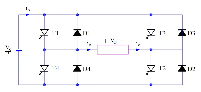
fig: 1`phi` full bridge inverter circuit diagram (`T_1,T_2,T_3,T_4` are fully controlled switches and `D_1,D_2,D_3,D_4` are body diode thast make them bidirectional)
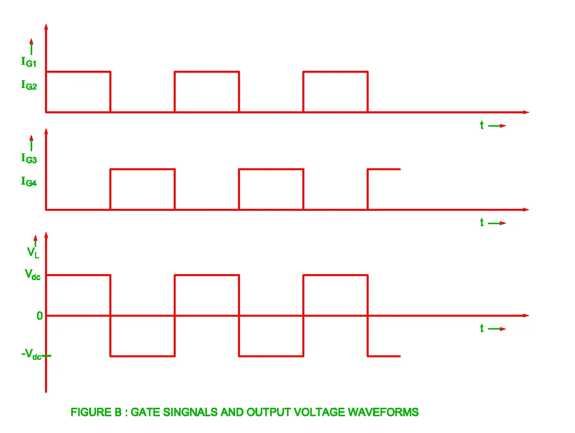
Fig: output of 1`phi` full bridge inverter. AC in nature as Repeating and both polarity
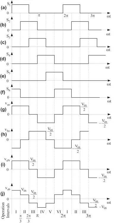
Fig: 3`phi` full bridge Inverter output. used for control of 3`phi` Induction Motor (j)
3. Chopper: Input and Output both are DC in nature.
can be step up and Step down . Used in speed control of DC motor
Step Down Chopper is extensively used in speed control of DC motor. Also known As the Buck Convertor.
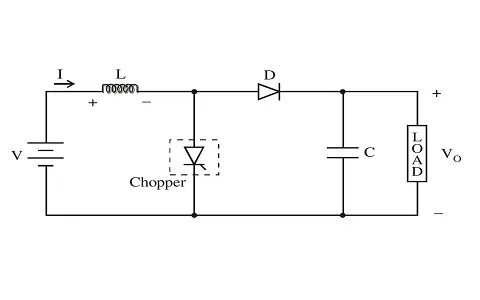
fig: circuit of Step Down chopper
dotted part denoted as a "Chopper" is actually a Fully controlled Switch such as SCR, GTO, BJT, MOSFET, etc. while the D is the Diode. it maintains continuity due to its frewheeling action.
The L(inductor) and C(capacitor) is forming a LPF(low-pass filter) for eliminating harmonics. The high inductance of the load the current fairly remains same and can be considered as a contant current source.
Duty Cycle: `delta or D`
since we are switching ON and OFF the Fully controlled Switch (here shown as chopper) we have to make a variable to find the ratio for how long the swtich is ON and OFF with respect to to the total Time Period.
`=>D = T_(ON)/T_("total")`
`= "ON Duration"/"Total Duration"`
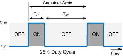
Fig: figure to depict Duty Cycle - here 25%
Application in Vehicles: speed control of DC machine through 'Armature Voltage control method' for `omega<omega_(base)`
-------------------------------------------------------------------------------------------------------------------------------------
2. An Electric Vehicle's powertrain with 72V battery pack in shown in the diagram below. The duty ratio for acceleration operation is 'd1' and for the braking operation the duty ratio is 'd2'.
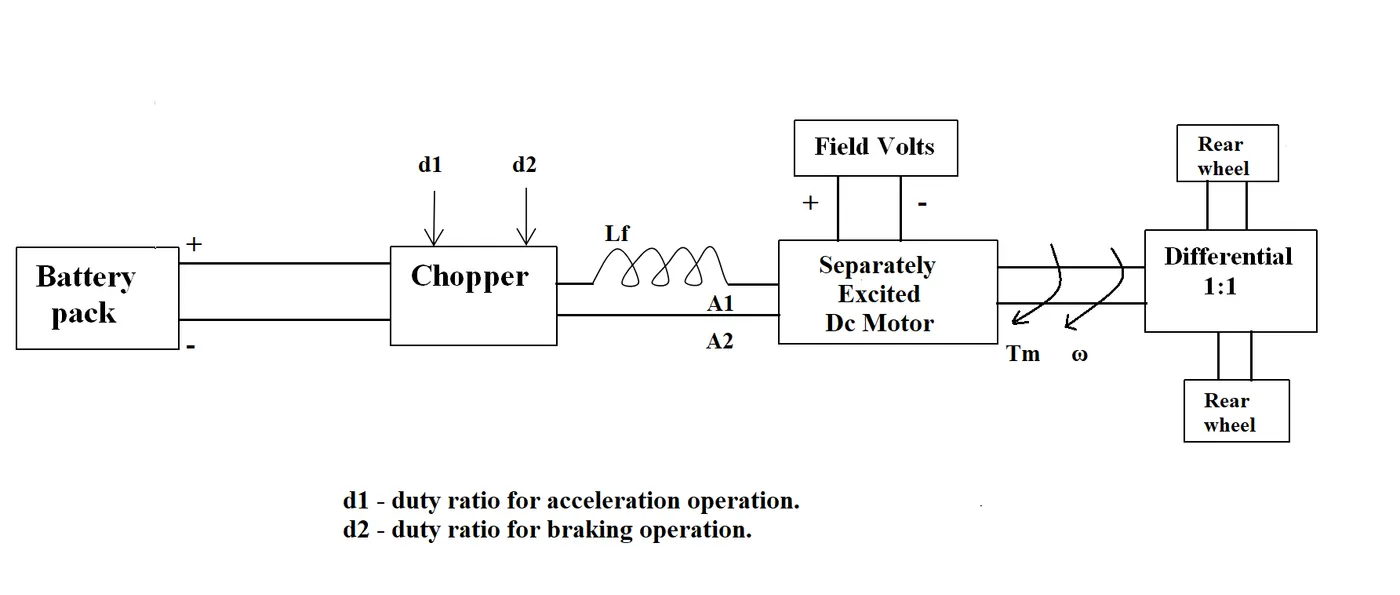
The other parameters of the electric vehicle is given below,
Motor and Controller Parameters:
Rated Armature voltage= 72 V
Rated armature current= 400 A
Ra= 0.5Ω, KΦ= 0.7 Volt second
Chopper Switching frequency= 400 Hz
The vehicle speed-torque characteristics are given by the below equation

What is EV steady state speed if duty cycle is 70%?
Solution 2:
Here for the Traction of the Electric Vehicle we have used Seperately Excited DC Motor.
So the voltage applied as an input to the motor will be DC in nature which is provided by the battery pack having Nominal Voltage of 72V as given in the Question.
so in this case Source: DC as well as the Motor/Load: DC . Since we will need to control the operation of the DC motor since we need a variable speed drive.
`=> E_b = K_mphiomega_m = V_t - I_aR_a`
`=>omega_m = (V_t- I_aR_a)/(K_mphi)`
we cannot control I_a as it depends on the load but we can control `V_t`,`R_a` or `phi`
so we can have 3 methods of speed control .
Since we are using the Seperately Excited DC machine here the Voltage changes across the Armature does not affect the Field winding current as both windings are excited seperately.
so the flux in the machine is not affected when we use the Armature Voltage Speed Control as the Voltage across the field winding is seperate and therefore
`=> phi = "constant"`
as `=>I_f = V_f/R_f = "constant"`
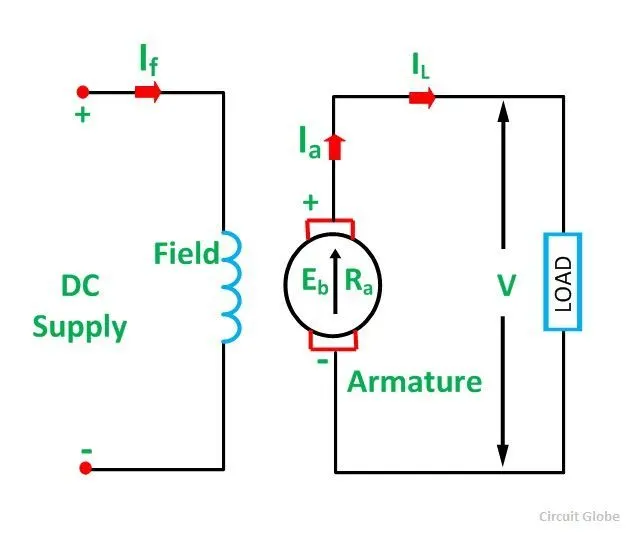
Fig: Circuit Diagram of seperately excited DC Motor
so as `=>I_a = (V-E_a)/R_a`
as V`downarrow` then `I_a downarrow`
and `tau_m propto I_a` as `[phi = "constant"]`
so `tau_m < tau_l` so it will decellerate and so Speed `downarrow`
but as speed `downarrow` and as we know that `E_b propto omega`
`E_b downarrow` so as `=>I_a = (V-E_a downarrow)/R_a`
then `I_a uparrow`
and as `tau_m propro I_a` `tau_m uparrow`
until it finds a steady point when `=>tau_m = tau_l`
but during this process the speed was decreasing `downarrow` and therefore this new operating point is such that
`=> omega < omega_(base)`
therefore, this Voltage control method is applicable for speeds only less than that of the base/rated speed of the motor
so this will behave As a Constant Torque drive as long as `=> omega < omega_(base)`
all this can be sum up in this image
Fig: depicting contant torque drive when `omega<omega_(base)` where Armature Voltage Control can be used for speed control
so here we will be using the Step-Down Chopper as `V<V_(rated)` as this method can work for only less than `omega_(base)` speeds.
Step Down Chopper is extensively used in speed control of DC motor. Also known As the Buck Convertor.
fig: circuit of Step Down chopper
dotted part denoted as a "Chopper" is actually a Fully controlled Switch such as SCR, GTO, BJT, MOSFET, etc. while the D is the Diode. it maintains continuity due to its frewheeling action.
The L(inductor) and C(capacitor) is forming a LPF(low-pass filter) for eliminating harmonics. The high inductance of the load the current fairly remains same and can be considered as a contant current source.
Duty Cycle: `delta or D`
since we are switching ON and OFF the Fully controlled Switch (here shown as chopper) we have to make a variable to find the ratio for how long the swtich is ON and OFF with respect to to the total Time Period.
`=>D = T_(ON)/T_("total")`
`= "ON Duration"/"Total Duration"`
Fig: figure to depict Duty Cycle - here 25%
Using Volt-Sec Balance:
for an Inductor- charging = discharging
`=>1/L intV_Ldt = 0 = DeltaI_L = I_f - I_i`
`=>intV_Ldt=0`
`=>(V_s - V_o)DT + (-V_o)(1-D)T = 0`
`=>V_o = DV_s`
as `D<1` so `V_o<V_s`
coming to our problem
for Duty cycle = 70%
`=>D = 0.7`
`=>V_s = 72V` (as battery pack Nominal voltage is given)
so `=>V_o = DV_s = 0.7xx72 = 50.4V`
so this means that the voltage applied across the DC Motor is Equal to `50.4V`
as the Speed-Torque characteristics of the DC motor follow the Straight line eqaution:
`=>omega = V_t/(K_mphi) - tau(R_a/(K_Mphi)^2)`
which will be something like:
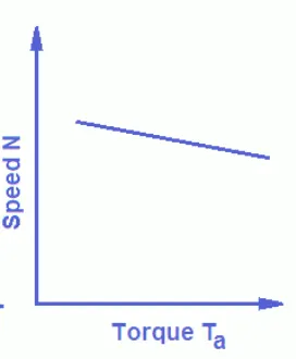
Fig: general Speed_Totque char of Seperately Excited DC Motor
Plot of our given DC Motor Speed-torque
`=>omega = V_t/(K_mphi) - tau(R_a/(K_Mphi)^2)`
Substituting the values of our Motor in the above equation we get:
Given -
`=>R_a = 0.5 Omega`
`=>Kphi = 0.7 Vsec = K_Mphi`
as the voltage across the motor is the Output voltage of the DC chopper
`=>V_o = V_t = 50.4V`
so the eqaution becomes:
`=>omega = 50.4/0.7 - tauxx0.5/(0.7)^2`
`=>omega = 72 - 1.02tau`
since we want totrque-speed char:
`=>tau = (72 - omega )/1.02`
`=>tau = 70.6 - 0.98omega`
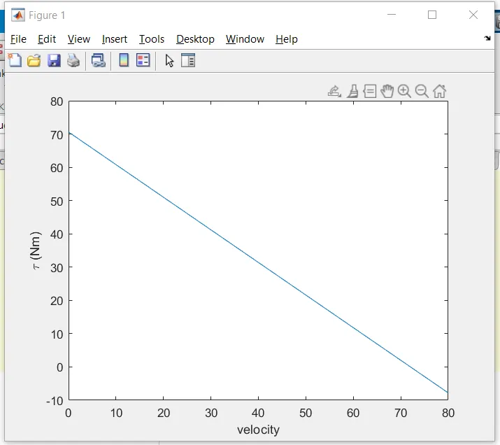
Fig: Torque-Speed char of DC Motor given to us in the problem
The Vehicle Characteristics
the following DC motor will have to satisfy the Vehicle requires speed torque char which have been provided by the equation:
this leads to a figure as
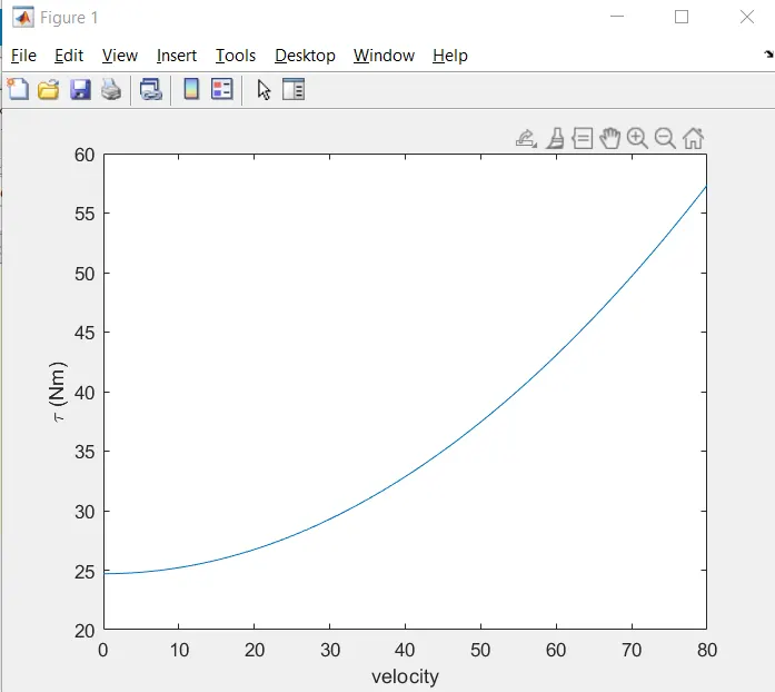
Fig: Vehicle Speed Torque Equation provided Implemented in MATLAB
so it follows a graph diffrent than that of our DC Motor.
so for steady state point we will have to see where both of these plots intersect with each other. This would tell us the Steadty State speed of the vehicle which the DC Motor will satisfy when the Duty cycle is equal to 70%
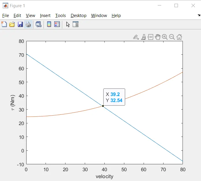
fig: both vehicle and Motor char in same figure. Plot reaches a Steady State at about 39.2 rad/sec
so the EV Steady State Speed at Duty Cycle of 70% is 39.2 rad/sec
----------------------------------------------------------------------------------------------------------------------------------------
3. Develop a mathematical model of a DC Motor for the below equation using Simulink.
ω= V/Kϕ -Ra/Kϕ^2 .T
Solution 3:
implementing the Equation using Basic Blocks in Simulink we arrive to the below Model .
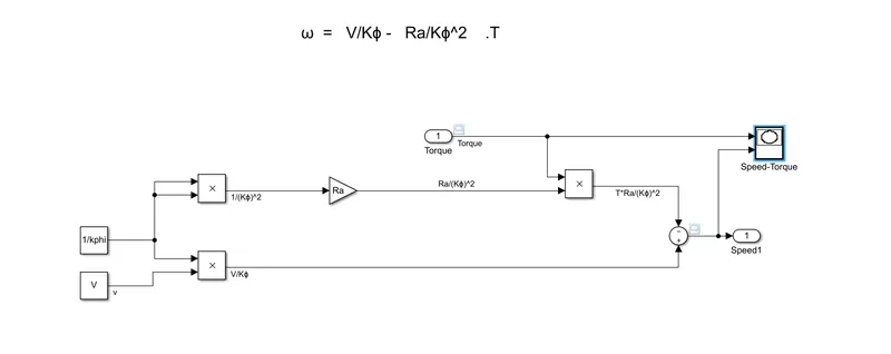
Fig: Equation implemented using Simulink blocks
input: Torque (as a contantly increasing signal from 0 at t=0 and 20Nm at t= 10)
output: Speed plotted as a result of calculation of the Simulink model
XY graph: to see the relationship between Speed and Torque with Torque on the X-Axis and Speed on the Y-Axis
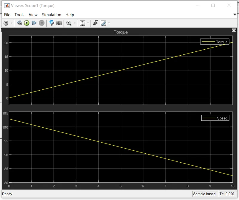
Fig: Speed and Torque plotted individually. Torque(Input) and Speed(Output)
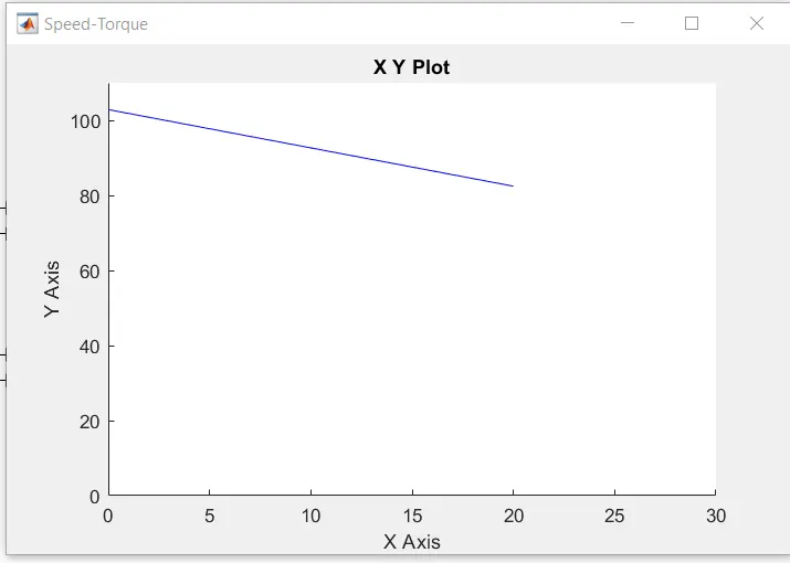
Fig;Speed-Torque char from the equation given . Similar to what we migh texpect from a DC machine. Straight line with Negative Slope
Fig: as we should have expected for DC Motor
----------------------------------------------------------------------------------------------------------------------------------------
4. Refer to the blog on below topic:
Induction Versus DC brushless motors by Wally Rippel, Tesla
Explain in brief about author’s perspective.
Solution 4:
Author first makes an interesting point as to why there cannot be one single 'fit all' type of motor or engine for all vehicles. This is because of the different requirements - In price and performance and use cases.
Hence there is the choice of DC Brushless motor as well as Induction Motor. Also that as technology evolves and develops we have more and better , efficient alternatives as time passes. For example the DC Brushed motor replaced by the DC Brushless motor due to better efficiency and the Use of Induction Motor due to developmemt of better controls for it. So nothing can be 'on size fit all' for a large time period.
DC Brushless Motor and Induction Motor:
Similarities
| Windings | 3`phi` distributed windings |
| Energy Source | Only 1 source of Electrical power (Armature winding) |
| Control | 3 `phi` modulating Inverter |
Differences:
| DC Brushless | Indcution Motor | |
| Stator | Permanent magnets used | Shorted Conductor bars |
| Starting | Inverter needed to start(maintain phase with angular position ) | Self Starting (no inverter needed) |
| Torque Performance | High | Low |
| Control code in Digital Controllers | High fidelity Position Sensor | Speed Sensor |
| Rotor Heat generation | Very Low | Low |
| Best operating power factor | 1 | 0.85 |
| Peak Point Efficiency | Higher | Relatively Lower |
| Average Efficiency | Relatively Lower | Higher |
| Losses | High as cannnot easily adjust B. Which leads to more losses in starting due to `I^2R` and more due to magnetic(eddy and hysterisis) at high `omega` and low `tau` |
B is controllable. And `B propto V/f`. So can reduce losses , for example at light loads (less `tau`) we can decrease the B by decreasing V and hence reduce magnetic losses. This can also be done to reduce Iron losses at high load,less speed. So an 'optimized efficiency' is obtained |
| Machine Size on Losses | as size grows, magnetic losses increase |
not affected much by size |
| Cost | Relatively Higher |
Relatively Lower. Inverter rating and hence cost also lower as 'Flux weakenign control' can be employed. Lesser back EMF hence lower protection circuit cost |
| Control Difficulty | Lower |
Higher. Complex Control |
| Stability | Higher throughout all Torque-Speed Range |
relatively Lower throughout all Torque-Speed Range adding to development cost but 'one time' and not recurring in nature |
Conclusion
so for high perfromance overall for PEV Indcution motors are a good fit because of their greater 'overall efficiency' due to controllable losses by virtue of its controllable B where `B propto V/f`
in HEV and PHEV DC Bruschless motor are 'good fit' because og High Torque to assist the Engine at starting , high peak point efficiency so added advantage as unlike PEV we dont need to use whole torque-speed range, and since lower size is required in HEV and PHEV , makes it less coslty and with lesser losses(as machine size `propto` losses for DC machine).