Stateflow - Control logic of State Machines (Washing machine and Gear Shift Logic)
- Implement control logic of a “washing machine” using Stateflow as per given sequence:
- If the power supply is available, the system gets activated
- If the Water supply is not available, stop the process & indicate through LED
- Soaking time should be 200s followed by Washing time of 100s.
- Then rinsing happens for next 20s & dryer runs for 50s
Solution 1:
Since we have to implement a logic and make transitions into different states for a state machine (here . the washing machine) we will need to implement the logic in the form of a flow chart/state chart.
we will be using the implementation of Stateflow for mode logic - where each discrete mode of a system is represented as a state.
the discrete modes of our system (washing machine) are:
1] soaking for 200 sec
2] washing for 100 sec
3] rinsing for 20 sec
4] drying for 50 sec
conditions for state transition: the state transition of the washing machine from one state to another is very simple and is led after the conditon of time delay is met.
other conditions: for the washing machine to operate it needs the supply of both electrical suppy and water. If either is not available the washing machine will stop working . But it is not exactly the same for both supply
condition for Power Supply: the washing machine needs power supply throughout the process or running, so we need to check in each state for power supply, if at any moment power supply is removed , for ex in an outage the machine stops working irrespective of the state it is in. All LEDs will be OFF since no power suppply.
condition for Water Supply: the machine needs water supply at 2 instances: during starting(for soaking) and for rinsing. If water supply is not available in those 2 stages then the machine stops working and repesents the problem in the water LED as RED color.
As an additional source of information the Running LED changes colour according to the state it is presently working in for the user to get an idea of the prcoceedings of the washing machine.
keeping this in mind we need the following contition checks.
1] at start : for power supply check is required to start the machine, if not present nothing will happen , this is our 'default transition'
2] at start if power supply is present : for water supply . If present machine will enter into the Soaking state, if the water supply is not present the machine will show a error by making water/stop LED as RED indicating the user that the machine has stopped working.
3] delay condition for transition into next stages: for each state the machine will operate for a specified time period as mentioned in the problem statement which are 200s for soaking,100s for washing,20s for rinsing and 50s for drying.
for the rinsing process the machine will need fresh new water to rinse the clothes and therefore needs water supply. So another cheack is required at this part of the process to see if it is present, if not the stop_LED again turns RED to show water error to the user
5] power supply throughout the process: if power supply goes out during any of the process the washing machine shuts down all the LEDs are OFF. we can even model the machine to start from where its operation terminated due to power outage but for the sake of simplicity it is not considered.
applying above logic in the stateflow chart:
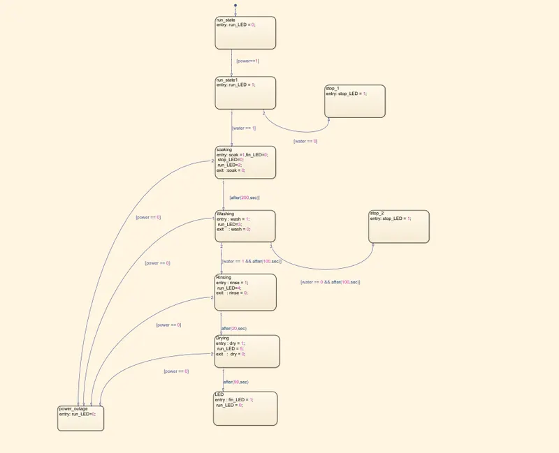
Fig: complete logic implemented in the stateflow for our state machine(washing machine)
condition checks mentioned above implemented in Stateflow(refer blue highlighted list)
1] at start for power supply:
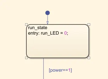
Fig: checkin for power supply before start of operation- deafult
2] at start for water if powrer supply present:
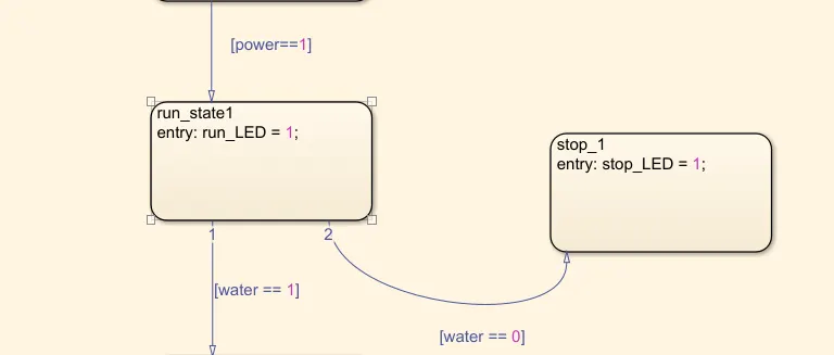
Fig: if water present start soaking else error LED of water and stop operation
3] delay for transitions:
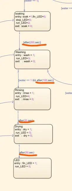
Fig: depicting dealy implemented as conditon for state transition
4] check for water supply before rinsing:
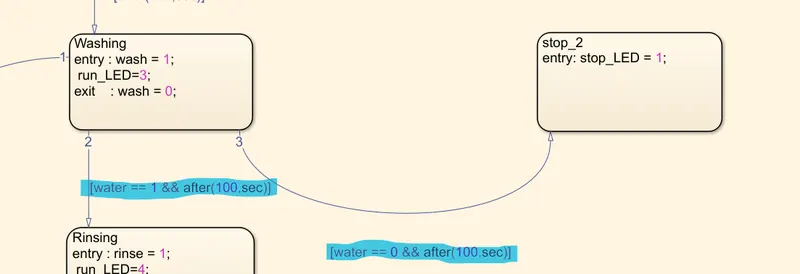
Fig: depicting checking water supplt for rinsing else error and Stop_LED RED
5] power supply throughout the process :
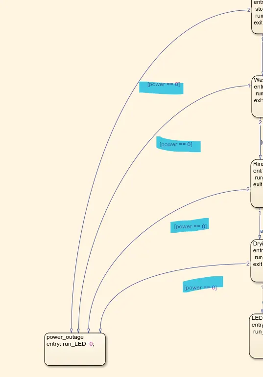
Fig: depicting if power removed at any stage machine stops and all LEDs OFF
complete Simulink Model:
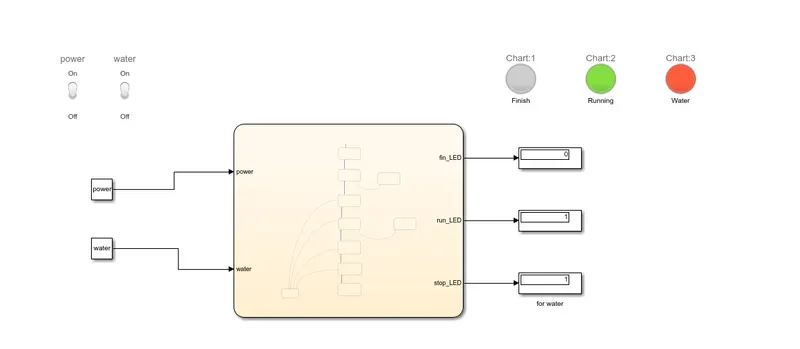
Fig: complete model with Stateflow chart , I/Ps, O/Ps, LEDs and Supplies
supplies: implemented as dashboard switches for ON/Off of power and water supply
Inputs to the stateflow: power and water supplies connected with switches. UP=ON=1, DOWN=OFF=0
outputs of the stateflow: fin_led: to show opeartion finished turns GREEN
run_LED: To show running of LED also gives state of which machine is in . GREEN- ON
BLUE- soaking, PURPLE- washing , ORANGE-rinsing , PINK - drying
stop_LED: to show if machine has stopped due to no water supply - RED.
WORKING:
scenario 1: run with both supplies on for all the time
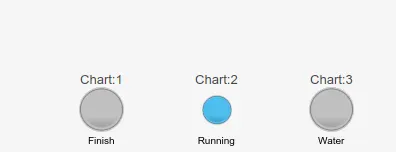
Fig: BLUE- machine in soaklng state
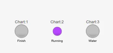
Fig: PURPLE- machine in washing state
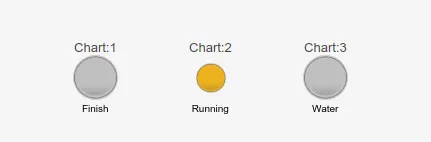
Fig: ORANGE- machine in rinsing state
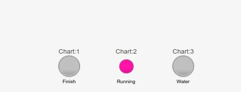
Fig: PINK- machine in drying state
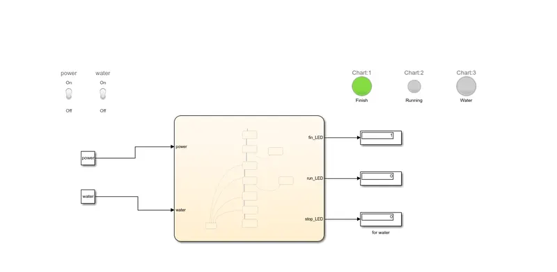
Fig: whole operation completed. Finish LED GREEN showing operation complete
scenario 2: no water supply from begining - user forgot to turn it ON
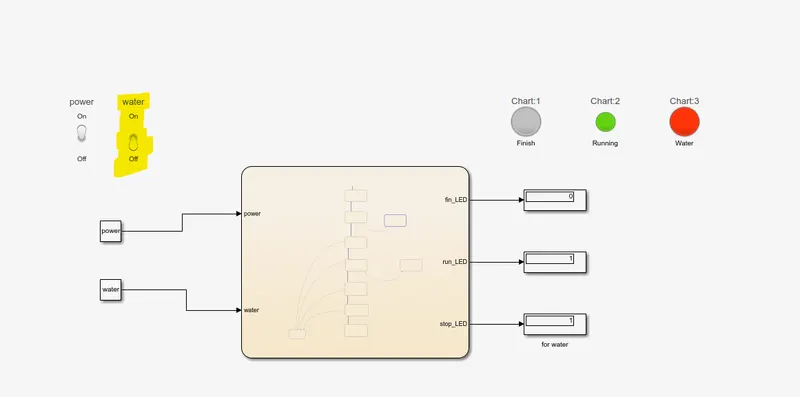
Fig: shows Water supply OFF. Run_LED GREEN depicting power present. stop_LED RED showing machine stopped due to no water supply
scenario 3: water in first part of operation but not available for rinsing(Use case: User's water Tank emptied)
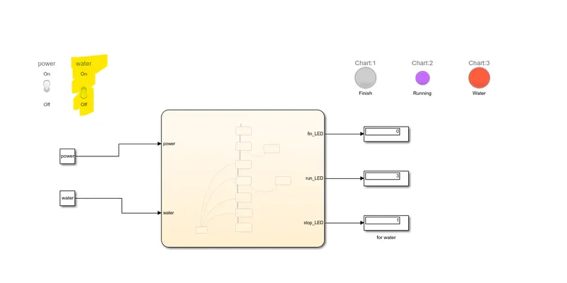
Fig: Stopped water supply after intial conditon. run_LED PURPLE depicting machine was in washing state prior. Stop_LED RED depicting machine stopped due to no water supply.
scenario 4: power supply removed during any part of operation(Use case: Electrical Outage during opeartion)
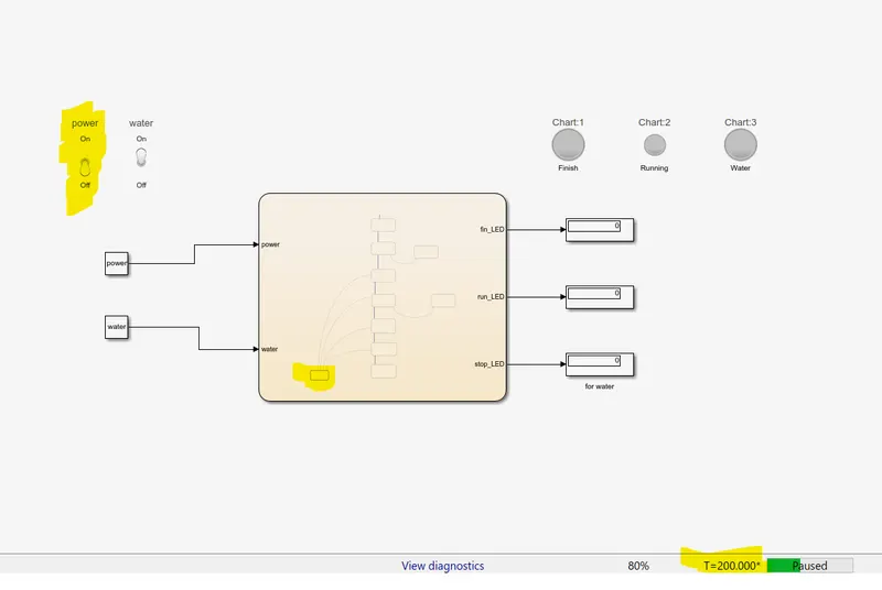
Fig: power outage at t=120s i.e. in washing state. All LEDs OFF depicting machine stopped operation and no power supply
Results: model respresents actual behavior of the washing machine closely under different conditons and scenarios.
----------------------------------------------------------------------------------------------------------------------------------------------------
2. Make a Simulink chart for the “Gear shift” logic as per below conditions:
Speed Range(kmph) Gear
0 to 15 1
16 to 25 2
26 to 40 3
41 to 60 4
Above 61 5
Give speed input while the simulation is running & display the gear number.
Solution 2:
This is a state machine since its State (which i this case is a gear ) will change depending upon the conditions and values of the Input (which in this case in speed).
depending upon the conditions and changes in the speed of the vehicle(which is an 'event' for this system)
the operating mode of our system which is the gear of the vehicle will have transition into another vehicle depending upon the speed limit.
Velocity input characteristics :Also notice that since we are trying the model a vehicle so the changes in the speed will be gradual, that is for example, if the speed of the vehicle at t=5 sec is 25 km/hr then it is not possible for it to change suddenly say to 40 km/her at t=6 sec. Therefore in this cas we wil take the input of the speed as gradually changing in a way that represents the actual real-life behvior . So in the case mentioned where the speed is 25 km/hr at t=5 sec the next moment it will be in the vicinity of 25 km/hr example 23km/hr in case of hard braking and 26km/hr in case of accelerating. Therfore the Velocity input will not have sudden extrem changes such as modelled by a step function.
Implication of the nature of Velocity input: this implies that if for example the Vehicle is operating in 4th gear and npow brake is applied then the speed will gradually decrease and first it will go to the 3rd gear and then 2nd depending upon the speed.
So the chnages in the gear can only take place to the immediately before/higher and immediate after/lower gear.
this implies that the 'Transitions' between adjacent gears are 2 in number : one for above speed limit and other for below speed range for a particular gear.
this is illustrated as below;
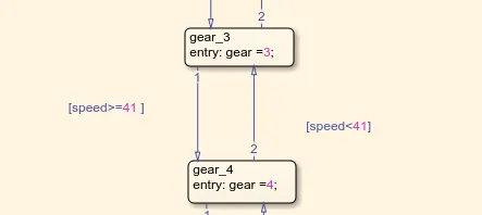
for example, here between gear 3 and gear 4 there are 2 connections
if spped >=41 then we should move to gear 4 as per our condition of speed ranges, similarly if the speed<41 the gear shifts to gear 3 as per speed ranges
but, there can't be a gear change from say gear 5 to gear 2 as that abrubt change still has to go through the gears lying in between so that is why such connections , such as gear 2 to gear 5 and vice versa are not required.
the Gear-Speed logic implemented as Stateflow chart:
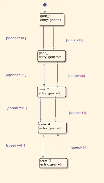
so according to changes in speed the transitions between the different gear takes place
the default transition path : is provided for gear 1 since whatever may be the case the vehicle will start initially from a rets position of 0km/hr irrespective of the drive cycle.
Speed input: since we want to see the capability of model to move up as in case of accelerating and also move down as in case of braking , the speed imput will be a custon signal where it is such that the speed changes in such a way that the gear transition takes place up as well as down depending upon the speed ranges.
for this I have use a Signal Builder block and created a custom signal . Again the changes in the speed should not be abrupt and they are not so as can bee seen in the speed Vs time signal
Speed Vs time Input signal :
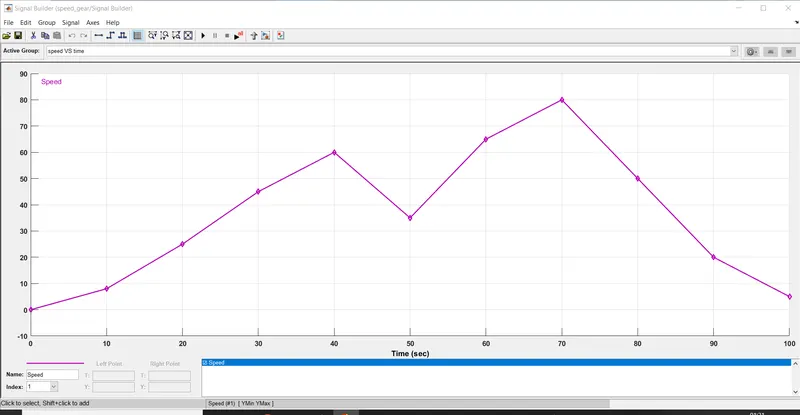
this signal shows that the speed varies both positively and negatively in such a way that both type of gear transitions occur. And also no abrupt changes to best represent real-life behavior.
Gear Output:
this is seen simply by creating a variable of named 'gear' of Type: Output Data

Stateflow chart for Speed-Gear State Machine has :
1 input : speed
1 output : gear
Complete System: stateflow chart + Inputs /Outputs
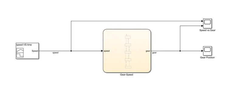
Total Simulation time: 100 seconds
Gear output plot:
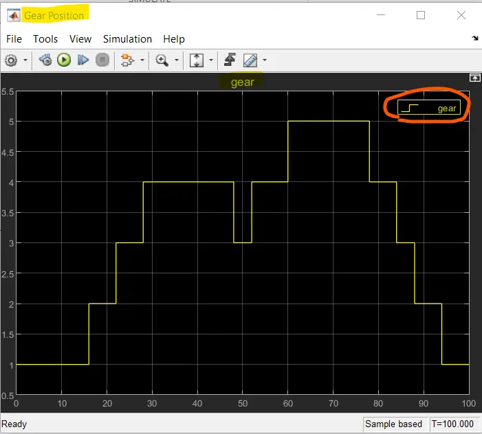
for better comparison and validation a plot of speed input and gear position is also provided:
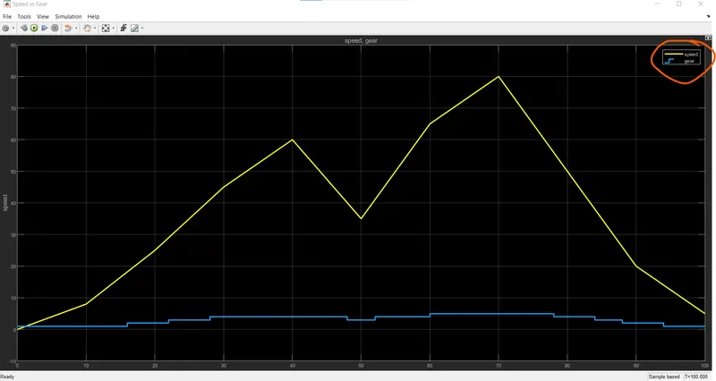
Results: the transitions of gears take place as expected in both cases: for increasing speed and decreasing speed.
----------------------------------------------------------------------------------------------------------------------------------------------------