Simulink model of A Doorbell and a Temperature-Controlled fan
- Make a Simulink model of Doorbell using solenoid block with the following details:
In the above arrangement, when the switch is closed the electromagnet receives electrical power from the battery and pulls the metal arm to hit the bell producing sound.
Create a situation where the switch is closed for 2 seconds and then released. Observe the physical movement of the plunger.
1) solution:
since we see in the above arrangement when the switch is ON then the metal arm is pulled and hits the bell producing sound.
for the purpose to convert electrical energy to mechanical enrgy we are using a solenoid here.
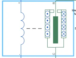
this is the block for solenoid and under the block parameters we see that there are 2 options for the movement of the punger in a solenoid . as it is explicitly explained in the question and can be seen in the diagram too, plunger is hit when the electric force pulls it inwards which is shown in the option under the "Motion direction under excitation" parameter for this case to represent the sysetem accurately.
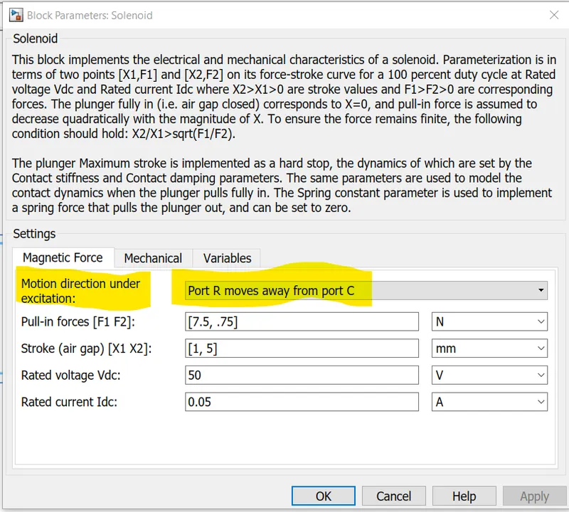
explaining Solenoid parameters:
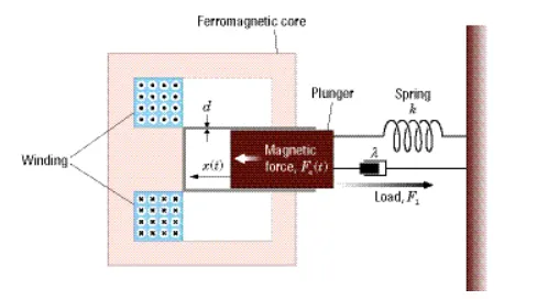
this illustrationj shows the working of the solenoid and the physical forces acting on it

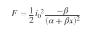
this is the Force-Stroke relationship of the solenoid and consists of 2 constants that define the solenoid as Alpha and Beta so we need 2 point to get 2 set of eqautions to solve the values of both. Hence we need to provide 2 values for both pull min forces and air-gap as can be seen in above parameter picture.
we have to take care of the condition
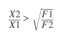 since as we know the force will decrease as the plunger moves away from the solenoid because thre magnetic forces follow the inverse square law and hence should satisfy the condition given for Force-stroke inputs.
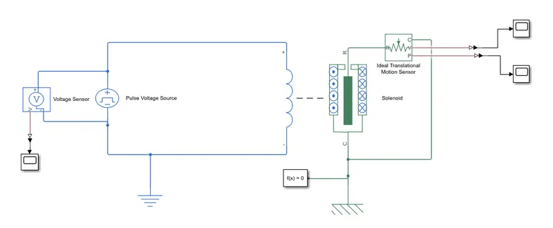
Now we need to create a situation where the electrical input is ON for 2 seconds for that we need a voltage source as an input to the solenoid,
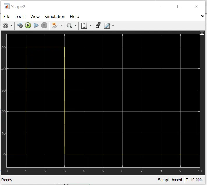
fo that i will use a pulse voltage source with a delay of 1 sec(for the sake to observe the response relationship) and a width of 2 secponds.
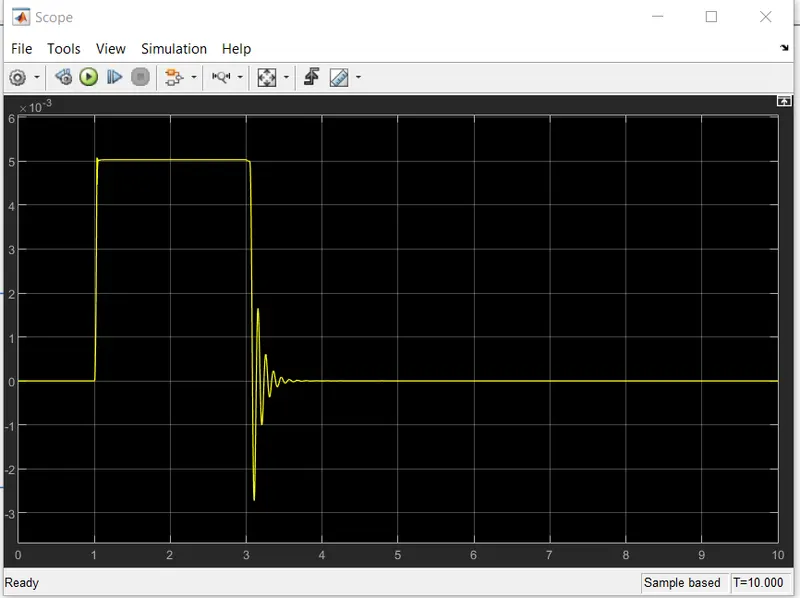
this input will drive the electrical side of the solenoid and will give a response in mechanical form(translational) due to the movement of the plunger of the solenoid.
this mechanical movement in the physical domain will be first sensed with the help of an ideal translational motion sensor 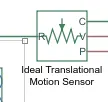
this give out a physical signal and will be converted into a simuluink signal using a PS-Simulink converter and then be plotted using a scope to see its response.
same we will use for measuring the input from our Pulse voltage source by using a Voltage sensor 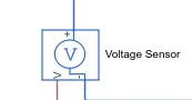
this will again give out a Phyical signal which will be converted into a simuluink signal using a PS-Simulink converter and then be plotted using a scope.
the model created to represent the system is:
plotting the input voltage from the Pulse Voltage Source:
plotting the response of the system(Translational Position of the plunger)
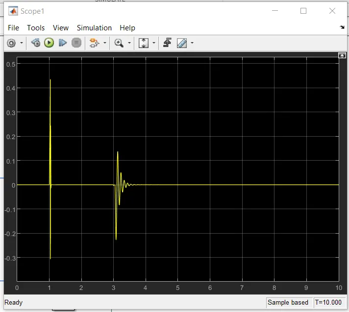
and the Tranlational Velocity of the plunger:
total Simulation Time: 10sec
solver configuation : Default
---------------------------------------------------------------------------------------------------------------------------------------
2. Use a thermistor to sense the temperature of a heater & turn on or turn off the fan as per below conditions:
Temperature source: 20 °C from 0 to 10 seconds, 27 °C from 10 to 30 seconds, 23 °C from 30 to 50 seconds
Fan conditions: ON if the temperature above 25 °C, OFF otherwise
solution 2:
Developing the Temperature Source:
As per requirement we see that we need a temperature source that can be controlled , So we need a controlled Tempearture source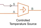 this Temparature source will maintain a constant Temperature across the terminals A and B , in other words, an ideal source. The contorlling input signal is applied through the Port S from where a Physical signal is applied.
developing the input signal according to the question:
since we need a signal which is variable and is having differnt values for each time stamp we need a block to create a custom signal. For this i have used a signal builder block
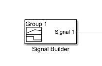
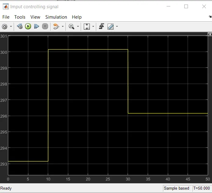
straing from the pulse input and defining the time-Temperature realtion we get the following graph.(note that the temperature is defined in Kelvins while in the question it is Celcius) This has been done just to maintain uniformity of the system as the Temperature in them Thermistor is also in Kelvins as we will see later on.
So the output from the signal builder block which will control the operation of the Controlled Temperature Block is Plotted below:
temperature(in Kelvin_) Vs Time(in sec)
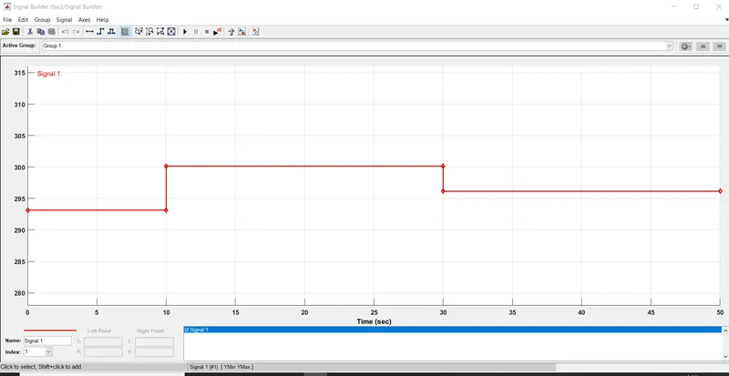
this is the controlling signal for our Controlled tempearture source:
using the Thermistor:
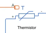 the thermistor block represnts the system to convert the Physical Temperature input into the T port which will affect the value of its resistance depending upon the temperature at a particular time stamp.
the resistance changes according to the equation :
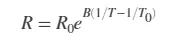
so when the input varies the Resistance varies and hence also the voltage across it.
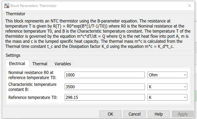
here are the values used for parameters of thr thermistor in our system with the refernce Temperature and T0(25C or 298.15K)
The Circuit to power our Thermistor:
for that i have used 50V DC voltage source and an additional resistor the purpose of using the additional resistor is to be able to see the changes in voltage drop across the thermistor due to its changing Temperature.
logic to switch ON/OFF the fan:
what we need now is to come up with a system that will decide when the fan should be ON and when OFF as our condition is :
On when temperature is >25C or 298.15K
for that we know the resistance of the Thermistor chnages with temperaure and hence the voltage. So i have used a Voltage sensor across the Thermistor to sense if the temperature is above or Below 25C
the Threshold condition: Voltage across Thermistor when Input Tempearure is 25C
we see that when the imput temperature is 25C or 298.15K the Voltage across the Thermistor is 49.96. this is the threshold value of our thermistor.
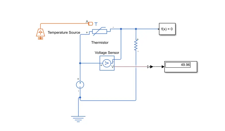
Taking action according to the value
switch: for the implementation of the logic that we need to switch on the fan when Temperature is above 25C and Off when below it. we use a Switch.
logic: as we know the Resistance will decreas with increase in tempearture for the Thermistor, when:
Temperature>25C Resistance is lower and hence Voltage is also lower and vice versa
Hence For the switch:
voltage > 49.95V Fan is OFF, Switch OFF Hence Input = 0
and of voltage < 49.95V Fan is ON, Swith ON Hence Input = 1
so the model with the switch and the varying input is:
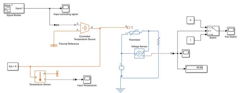
There are 3 scopes:
1) input controlling signal: input to control the Controlled Temperature source created by the signal builder
2) Input Temperatue: to see what actually is going into the Thermistor Control signal Port (Port S), as a rain check
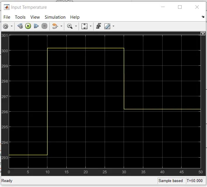
3) Fan switch: this represents the state of the Fan
1 meanas the Fan is ON and 0 means it is OFF.
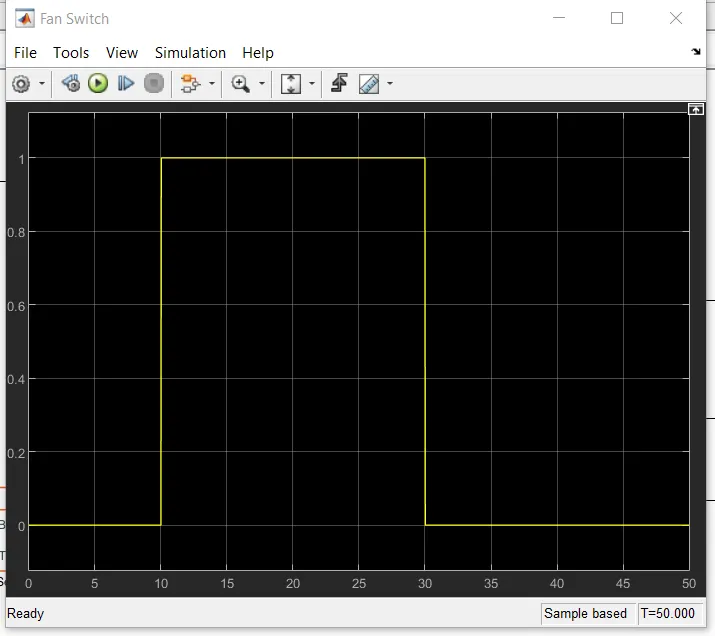
results: so we see simulation is correct as the only time temp>25C is from t=10s to t=30s where it is Temp=27C
simulation time: 50 seconds as specified in the problem statement.
-------------------------------------------------------------------------------------------------------------------------