Week-7 Challenge: DC Motor Control
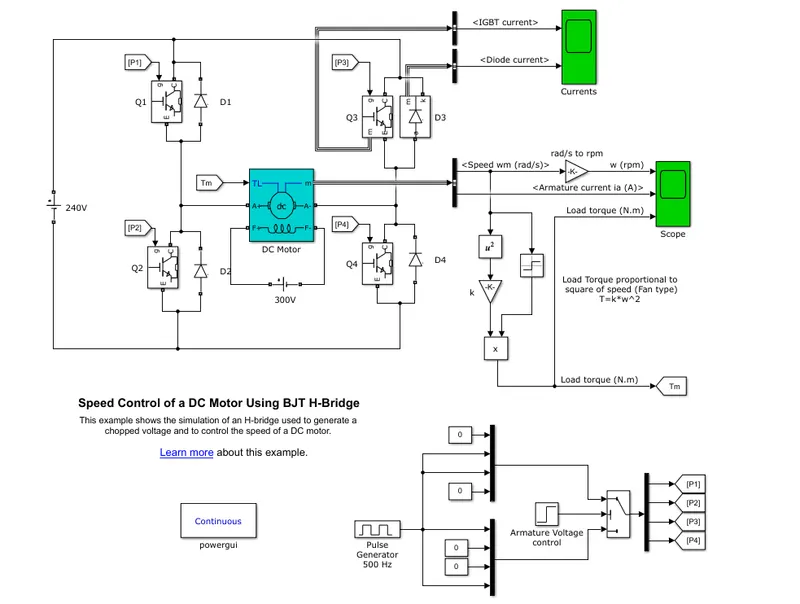
Fig 1 : a model of H bridge
Here model will show the H bridge .its will resemble the letter H in the alphabet so it's called so.
Now here 4 MOSFETs will be used as switches and to control the flow of electricity from the source to the load that is the DC motor . Sources used here are 240 DC sources.And for execution, we are using 300 V dc sources. here along with using 4 MOSFET DIODE will be used as a freewheeling diode.
To check the output we had taken the output from one of the MOSFET and all current through the MOSFET and Diode can be seen.
and the output is taken from m and is connected to the bus. In the bus, speed is taken and it's given to the output through a gain block. And current through armature is given directly to the scope. according to the equation of
Speed of fan=constant * speed^2
so we need to multiply the speed and constant value need to be insrted.
And here in All MOSFET, we have to give the Gain Value so for that lets consider a gain with 500 Hz frequency. And that has been given to the bus with some constant. And that constants have been given to Switch and output is taken from the bus. And values were extracted to each value.
output is:
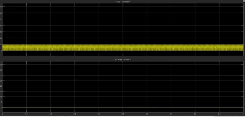
Fig 2:-Current are IGBT and Diode.
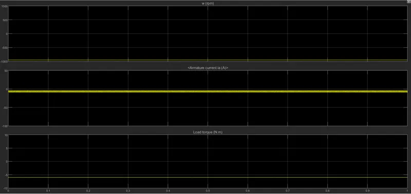
Fig3:-output as shown.
B:-Aremature current will be governed by this example
as speed is negative and it can be seen that current is also negative with some implication with it.
C:- difference between h bridge and Dc 7
| Sl No | H Bridge | DC 7 |
| 1 | input is given in DC | Input given is in AC |
| 2 | it is simulated in continuous mode | it is simulated in discreet mode |
| 3 | Here it works as a separately excited motor | No excitation is given here |
| 4 | Here we main aim to see only see the speed and torque | Here we are going to see the Duty cycle, Speed and Current. |
| 5 | Here we won't consider reference speed | Here reference speed is taken |
| 6 | it works for 5 Hp motor | it works for 200 HP drive |
2:-Two Quadrant chopper operations.
In power electronics, a chopper circuit is any of numerous types of electronic switching devices and circuits used in power control and signal applications. A chopper is a device that converts fixed DC input to a variable DC output voltage directly. Essentially, a chopper is an electronic Switch that is used to interrupt one signal under the control of another.
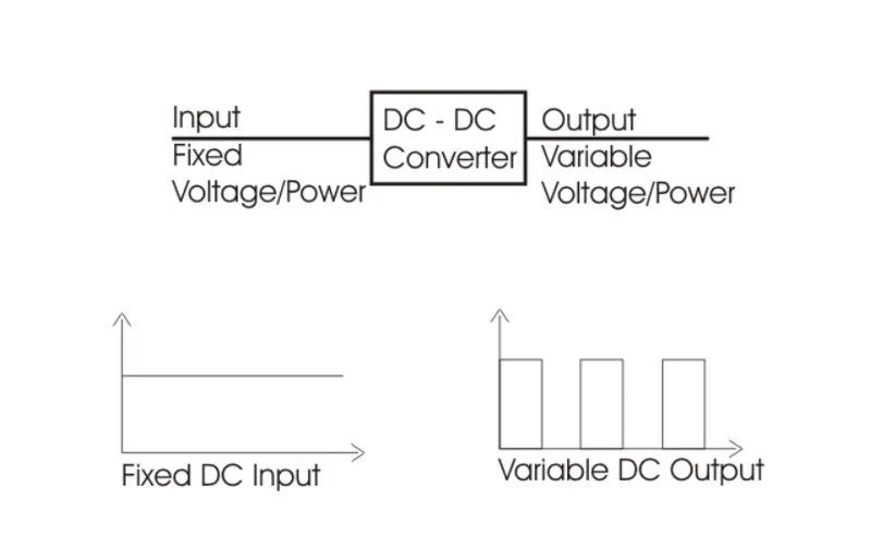
Fig 4:-Chopper in use
and depending upon its application its can be classified into 4 quadrant choppers but in the question, its asked only for 2 quadrant operation so, its explained below
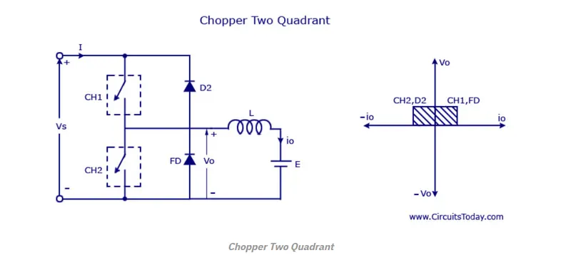
Fig 5:-Multi Quadrant chopper.
Here at one instant both CH1 and will be closed so the current will flow in the direction of CH1 and FD 2 will charge.When ch2 will close. Once CH2 will be closed then D2 will be closed. So either CH2 and D2 will be closed or CH1 and FD will be open.and we had simulated the same in the Simulink As shown below.
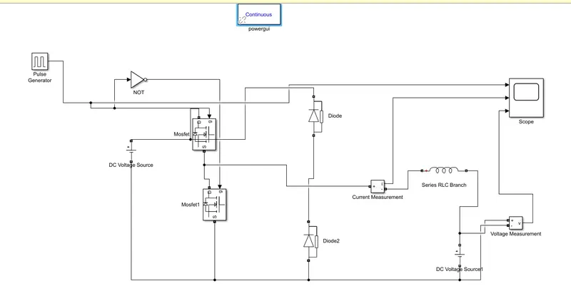
Fig 6:-2 Quadrant motor.
Its been constructed as 2 MOSFET and 2 Diode. And various current and voltage measurements. And a not gate will be used. And it has 2 voltage sources.Usually, V1 will be half of V2. And scope will have to see the output.
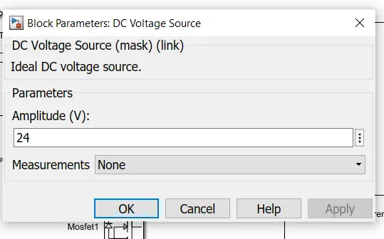
Fig 7:-Configuration of V1
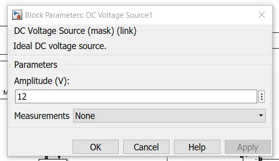
Fig 7:-Configuration of V2
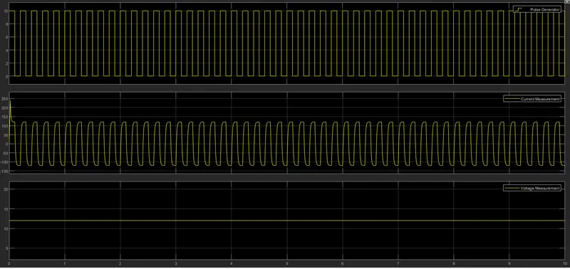
Fig 8:-Output of the entire model.
So we can see that input will be in constant voltage and output will be pulsating DC.
3:-Working of BLDC motor
Construction:-
Like any other motor, it has having
Stator:-which is stationary
Rotor:- which will rotate
The below figure will show these things
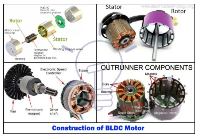
Fig9:- BLDC motor construction [from-electricaltechnology.com]
but here controller will work a major role and it was done by installing a hall effect sensor and its working is explained below
Hall sensor provides the information to synchronize stator armature excitation with rotor position. Since the commutation of the BLDC motor is controlled electronically, the stator windings should be energized in sequence in order to rotate the motor. Before energizing a particular stator winding, acknowledgement of the rotor position is necessary. So the Hall Effect sensor embedded in the stator senses the rotor position.
Most BLDC motors incorporate three Hall sensors which are embedded into the stator. Each sensor generates Low and High signals whenever the rotor poles pass near to it. The exact commutation sequence to the stator winding can be determined based on the combination of these three sensors’ responses.
Working of BLDC:-
BLDC motor works on the principle similar to that of a brushed DC motor.
The Lorentz force law states that whenever a current-carrying conductor is placed in a magnetic field it experiences a force. As a consequence of the reaction force, the magnet will experience an equal and opposite force. In the BLDC motor, the current-carrying conductor is stationary and the permanent magnet is moving.
When the stator coils get a supply from the source, it becomes an electromagnet and starts producing the uniform field in the air gap. Though the source of supply is DC, switching makes to generate an AC voltage waveform with a trapezoidal shape. Due to the force of interaction between the electromagnet stator and permanent magnet rotor, the rotor continues to rotate.
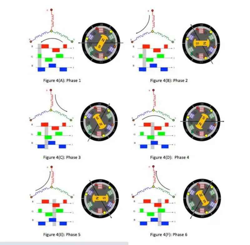
Fig10 : working of BLDC motor [EDN motors]
Here we can see that in the figure in the figure from 1 to 6 will show as shown above. the resultant fore will happen as if it is controlled by its electronic communication and as a result, it will rotate.
Advantages of BLDC motor
- Less maintenance
- Reduce size with lesser harmonics
- Higher speed and thermally more stable.
- lesser weight
- Electronic magnetic interference is less.
The disadvantage of the BLDC motor
- usually costly compared with the same rating of other motors.
- we are going to use an electronic driver which is very costly
- Need additional sensor.
Some of the applications of BLDC
- used in Electric vehicles
- Used in computer Hard disk, Washing machine.
Result :
- The entire h bridge will be discussed .
- We had gone through the armature current and the result is made.
- differences were written between H bridge and four Quadrant motor.
- 2 quadrant motors in simulated and a comment has been given on output.
- a note on the BLDC motor has been given with its limitation, advantages and Applications.