Week -2
- Make a Simulink model of Doorbell using a solenoid block with the following details:
Objective: Is to simulate the doorbell with a minimum of 2 seconds
process :
we need to take the following blocks in Simulink and they are
- Pulse generator
- scope
- ps converter
- Battery
- switch
- solver configurator
- solenoid
- ideal translator motion sensor
- eating for both mechanical and electrical.
by using the above blocks we need to make the circuit as shown below and in the diagram, we can see the 2 different colours green for mechanical and blue for electrical. solver, we had connected for electrical part. below are the images for all
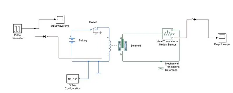
Fig 1:Model of solenoid
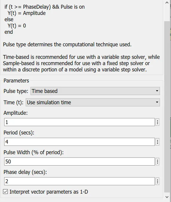
Fig2:Pluse generator
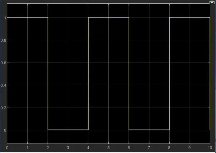
Fig3:Input waveform
And all of the conditions will be satisfied given in the question. in X is time and Y-axis is an aptitude
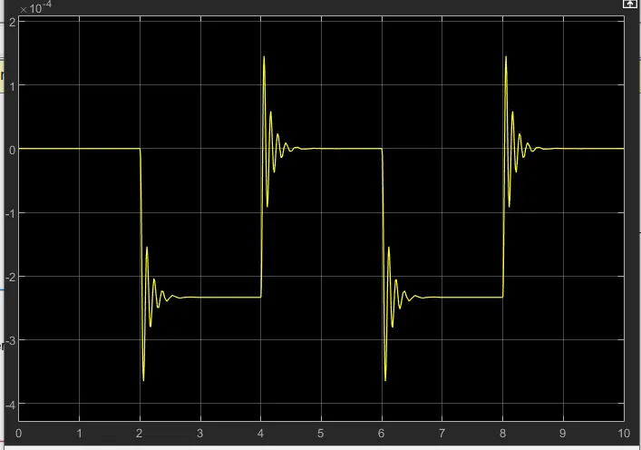
Fig4:Output waveform: some distraction will happen and the reason is explained in the result.
Result:
The experiment is simulated and below are the observation
- We can see the inverter input because of solenoid used in simulation
- it can be seen that fluctuation and that will happen because of closure of circuit and it happens by mechanical contact.
- The working of a solenoid is understood.
- Use a thermistor to sense the temperature of a heater & turn on or turn off the fan as per the below conditions:
Condition are:-
Objective
20 °C from 0 to 10 seconds off;27 °C from 10 to 30 seconds;23 °C from 30 to 50 seconds
fan need to turn for any temperature greater than 25 °C
So as per the given in question, we want to create a single generator so we need an signal generator .
then we wants to control the tempartutr so ,temperature Controlled Temperature Soure is requried.
for power battery need to be their.
so to measure the voltage weneed to measure across an resistor and voltage sensor need to be their.
solver need to be their and we need to put two different system ,namely simscape nad simulink.
and ps to simunilk and simuinuk to ps converter need to be their.
to check and set the axis display is necessary and with switch.
To check output scope need to be their.
Ground need to be their.
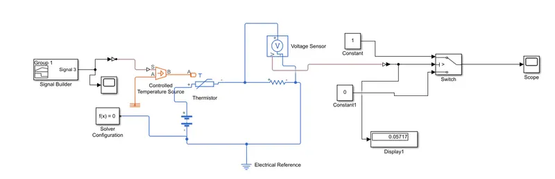
Fig 5:Entire model of temperature controlled fam controlled.
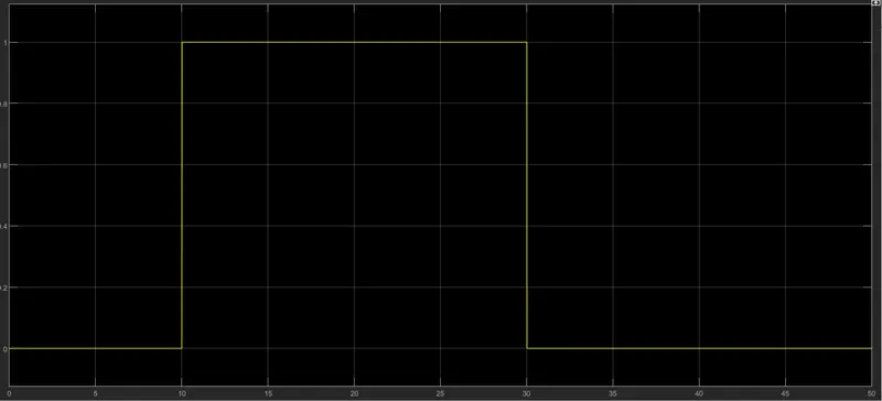
Fig 6: singal Builder output.
Here data is given in degree and we need to change it into farhanite for our caluclation.
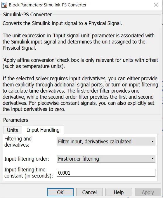
Fig 7:similuink -ps converter
here we need to change the input into filter for then only execution will happen.
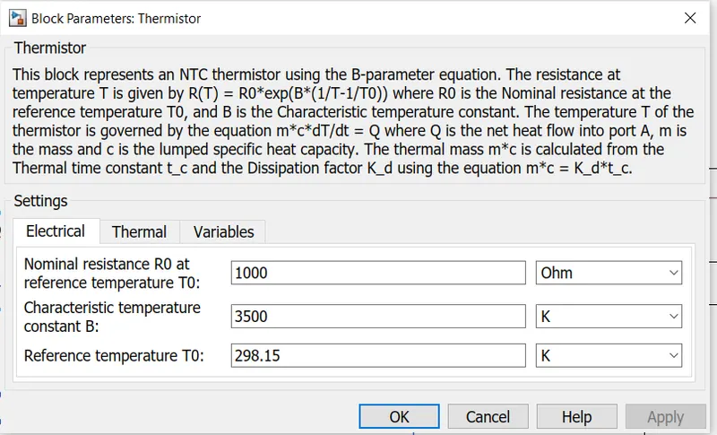
Fig8:Thermistor parameter view.
here the temperature in in farahnite so entire system need to be their in farahnite.
now after this voltage sensor will be their nad it will sense the voltage and it will give it to switch.
so for switch we need to select the thresould value so we need to select the value.
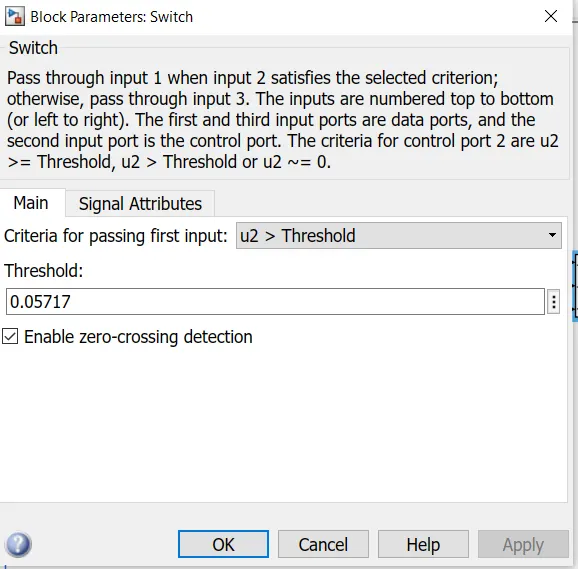
Fig 9:switch block
thresolud value is set as per value we will get from display.
than value will shown in scope as below shown.
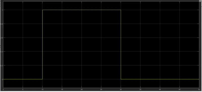
Fig10:scope value of model
Result
- Change the simulation time to 50 seconds
- After simulation scope value is as shown above for time 0-10 seconds & 30-50 seconds the output value is off and only 10-30 seconds entire system is on mode.
- The entire thermistor working is understood