Week-7 Challenge: DC Motor Control
Question 3)
Explain in a brief about the operation of the BLDC motor.
Ans:-
- Why BLDC motor? Advantages of BLDC motor over brushed type motor.
Whether BLDC motor loaded or unloaded it runs above 10,000 rpm
Less maintenance is required as there is no wear and tear of the brush. as well as it becomes then very reliable due to no brushes are used.
Among BLDC inner rotor motors have low rotor inertia which allows the motor to runs faster break faster or reverse quickly.
Elimination of brush gives noiseless operation, high efficiency, high-speed ranges.
Provides high torque with good speed control strategies.
- Componet present in BLDC motor .
It consists of a Controller and power converter.
Controller to generated PWM signals and Power converter which has six switches (semiconductor devices) to give Trapazioidal wave similar to AC wave.
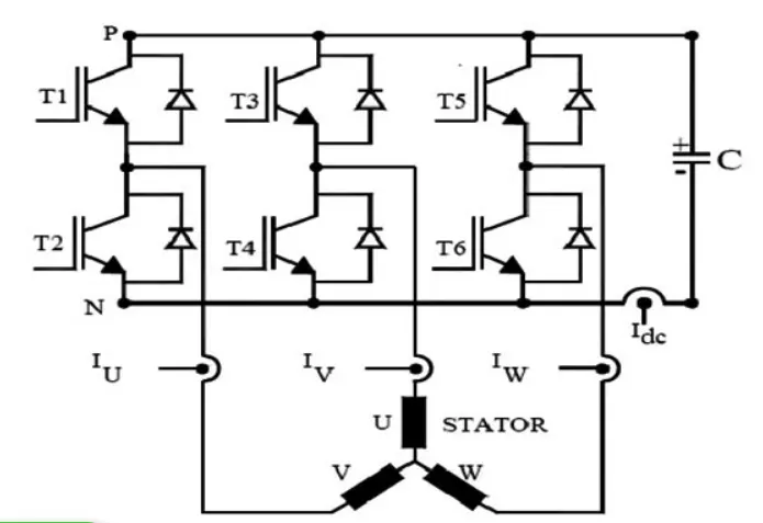
So by giving trigger signals to the appropriate thyristor three winding u,v,w can be energized according to the output given by Hall sensor.
Hall sensor.
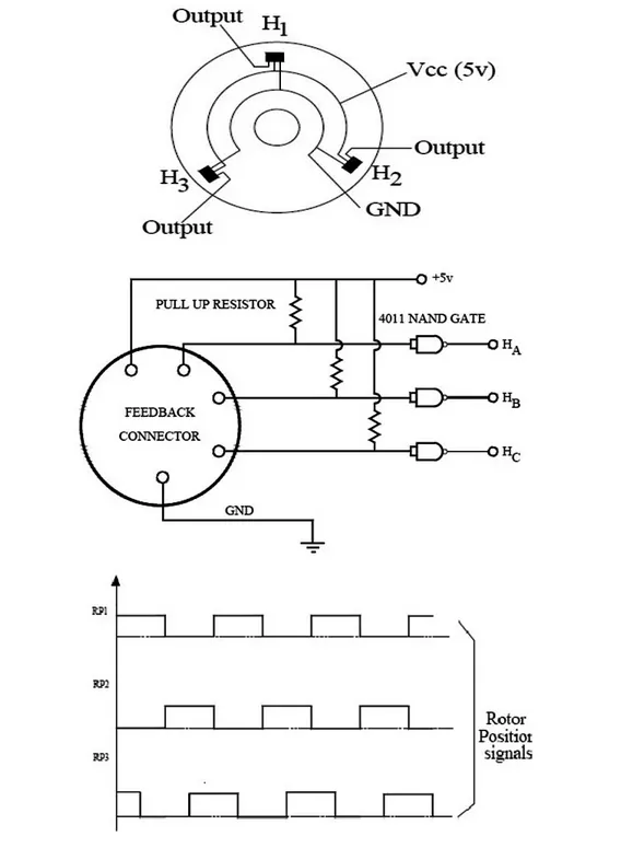
Hall sensor-generated output hall voltage when it is kept in a magnetic field. so these hall sensors are kept nearby poles to obtain the position of the rotor and then the controller can give a trigger signal to a particular winding according to the output of hall sensor. This three sensors can be placed 120 degrees apart and located at the stator frame. Hall sensor used to sense rotor position.
- Working Principle of BLDC:-
The trigger signals provided to each winding are in such a way that the roto must feel attraction/pull force from the upcoming pole and the present pole must generate repulsion/push force.
So these attraction and repulsion force contributes to smooth rotation of rotor as well as it can also generate maximum torque.
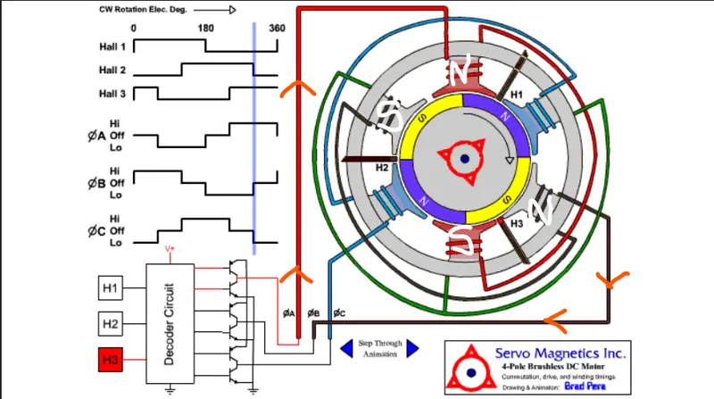
By proving signals from Hall 3 according to that here Phase A and Phase B are high so that 4 poles are generating north and south poles.
Reference- https://www.pantechsolutions.net/blog/bldc-motor-control/
Question 1)
1A) Explain a MATLAB demo model named ‘Speed control of a DC motor using BJT H-bridge’.
- Ans-
Separately excited dc motor's speed is to be controlled via H-bridge.
Specification of Dc motor used 5HP,240v,1750RPM,Field voltage 300v.
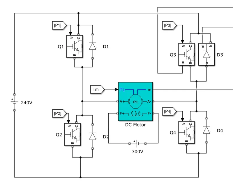
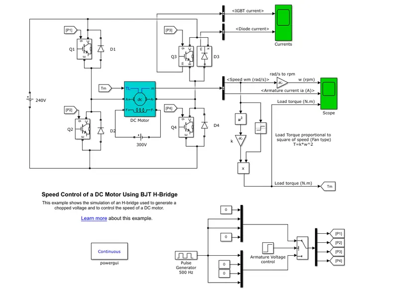
Four no. of IGBT and Four no. of Diode are used to form H-bride. The total structure looks like an H so the bridge calls H-bridge. A diode is connected in parallel with each IGBT.
The below Matlab model shows separately DC motor connected in H-bridge with IGBTs and Diodes.
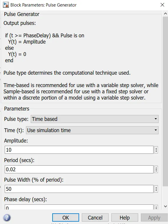
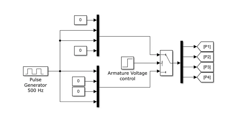
The below figure shows the Pulse Generator whose duty cycle can be changed to vary the speed of DC motor as well as this circuit provides gate pulse to each IGBT as per the requirement of operation according to in which quadrant motor is be operated.
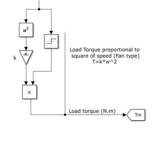
Fan type load is connected to DC motor whose equation is as follows.
Torque = Gain*Speed^2
Current through IGBTs -
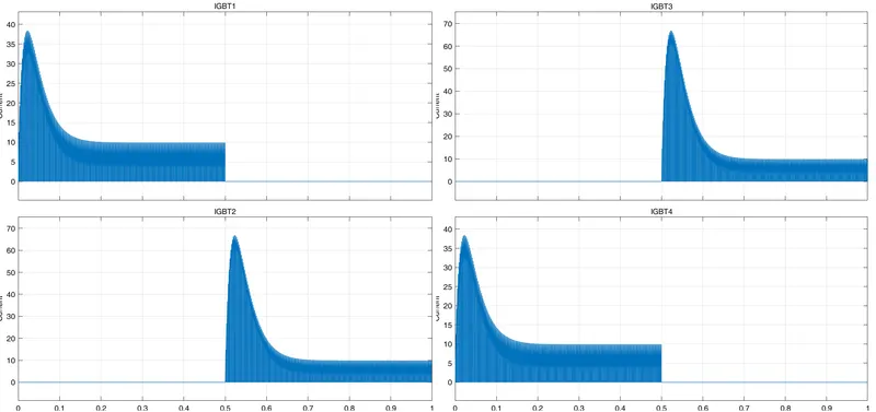
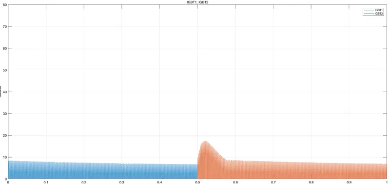
1) For the first 0.5sec IGBT 1 and IGBT 2 are conducting which means the motor is running in Forward motoring mode. 1st quadrant of operation. Where armature current and the output voltage is positive as well as torque and speed are also positive.
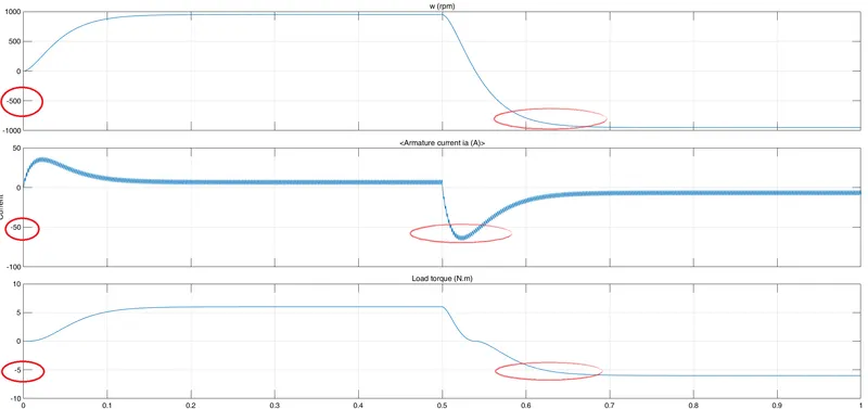
2) After 0.5 sec IGBT 3 and IGBT 2 are triggered so now armature current and output voltage become negative so the motor now starts rotating in an anti-clockwise direction or reversed. As the motor is rotating in a reversed direction so the load torque also becomes negative. now the motor is operating in the 3rd quadrant. Highlighted portion in the below fig shows load torque, speed, armature current on the negative side.
The complete model of Speed control of a DC motor using BJT H-bridge -
1C) Refer to the help section of ‘The Four-Quadrant Chopper DC Drive (DC7) block’. Compare it with the H-bridge model.
Ans -
In a Four quadrant chopper, there are four regions of operation which are as follows -
1) Forward motoring mode.
In which IGBT 1 and IGBT 4 operate and when IGBT 1 is off then Diode 2 and IGBT 4 operate.
Here the output voltage is positive and the armature current is also positive. So it satisfies the condition to operate in quadrant 1.
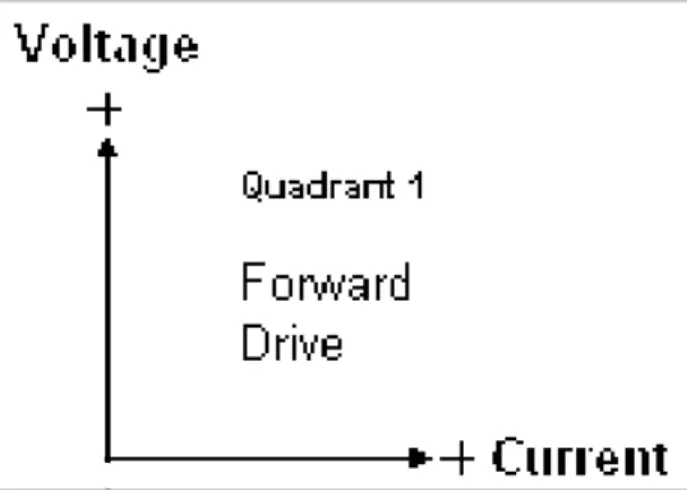
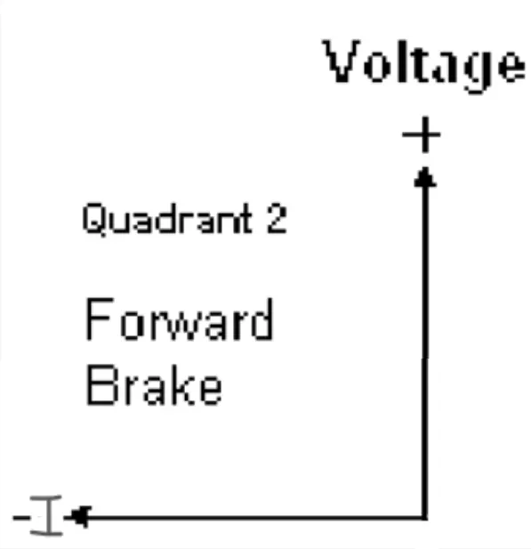
2) Forward regenerative mode.
Now IGBT 2 and Diode 4 are operated so here we can see the armature current is negative and voltage remains positive when IGBT 2 is off then whatever the energy stored by the inductor in the first case that now flowing through Diode 4 and Diode 1. So the quadrant of operation is now 2nd.
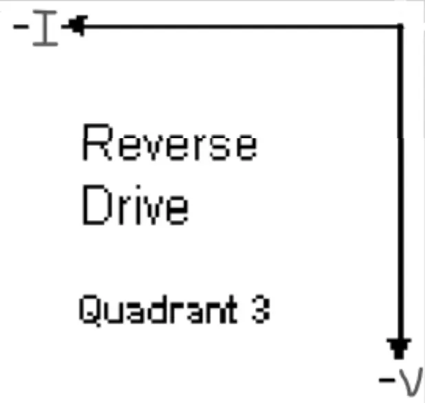
3)Reverse motoring mode.
Now the motor is rotating in the reverse direction as IGBT 3 and IGBT 2 are conducting. When IGBT 3 is turned off then IGBT 2 and Diode 4 will conduct. As both output voltage and armature current are in a negative direction so the operation of the quadrant will be 3rd quadrant.
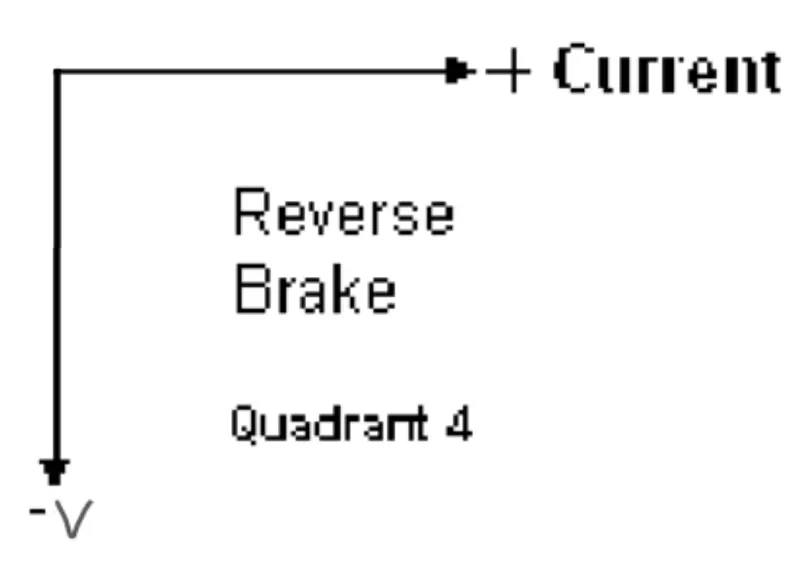
4)Reverse regenerative mode.
Here regeneration happens but armature current remains positive by conducting Diode 2 and IGBT 4 but when IGBT 4 is off then Diode 2 and Diode 4 conduct and which makes output voltage become negative. So here current is positive and Voltage is negative so it lies in the 4th quadrant.
Comparsion of Four quaderent chopper vs H-bridge.
1) Switching frequency of the four-quadrant chopper is high as compared to H-bridge which has a low switching frequency.
2)High switching frequency so a complex gate driver for MOSFET or IGBT is required for a four-quadrant chopper whereas less complex control is required for H-bridge ckt.
3)Four quadrant chopper work in four regions which are Forward motoring mode, Reverse motoring mode, Forward regenerative mode, Reverse regenerative mode and H-bridge can only work in two-mode forward motoring mode and reverse motoring mode.
4) In the case of a four-quadrant chopper Regenerative breaking is possible but in the case of H-bride Regenerative braking is absent.
5) H-bridge uses - Robotics. Four quadrant chopper - Industrial Equipment.
1B)
Comment on the armature current shoot-up from the scope results.
Ans -
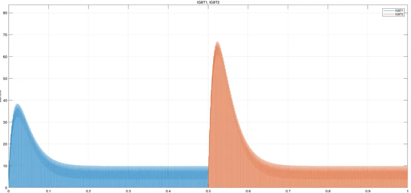
When Duty cycle = 75% [omega = 950 rpm Load torque= 6 Nm]
At t=0 we can see a blue spike of the current wave of a magnitude of 38 amp which is because of transient switching
and at t=0.5 there a large magnitude of say 68 amp of spike occurs because of suddenly changing the direction of the motor, before t=0.5sec motor was running in a forward direction but after t=0.5sec IGBT 3 and IGBT 2 got triggering pulse through pulse generator and the motor starts to run in the reverse direction. So due to this sudden changing of armature current we can see a high amplitude of current surge.
When Duty cycle = 50% [omega = 440 rpm Load torque= 1.3 Nm]
by decreasing the duty cycle from 75% to 50% current spikes also decreased a lot but along with that, duty cycle also affect speed of DC motor as well as the load torque generated by the motor.
Question 2)
Develop a 2-quadrant chopper using simulink & explain the working of the same with the relevant results. (Refer to article - Multiquadrant operation of motor )
Ans -
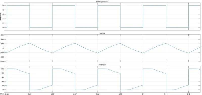
In the two-quadrant chopper, two MOSFET and two Diodes are used. Triggering pulse for a MOSFET is given by a pulse generator with a NOT logic gate so that both of the MOSFETs should not get triggered at a time in order to prevent from short circuit. A Machine is a model from an inductor and voltage source. The only inductor is chosen from RLC branch.
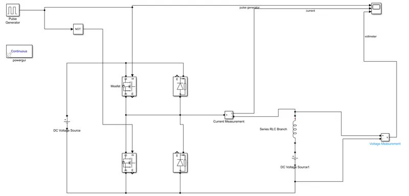
Amplitude is kept high in order to see a clear waveform. Frequency is kept 50Hzs i.e period is kept 0.02 as F=1/T.