Week-7 Challenge: DC Motor Control
AIM:
To control the DC motor with the given methods.
OBJECTIVE:
- Explain the model of ‘Speed control of a DC motor using BJT H-bridge’ and observe the Armature current results.
- Try to compare the ‘Four quadrant chopper DC drive block’ with H-bridge model.
- Create a Two quadrant chopper using Simulink and explain the working process.
- Briefly explain the operation of BLDC Motor.
1.A Explain a MATLAB demo model named ‘Speed control of a DC motor using BJT H-bridge’.
Simulink model for Speed Control of a DC Motor using BJT H-Bridge
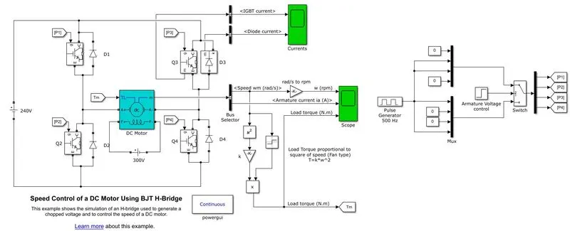
The Bipolar Junction Transistor (BJT) can be used for power switching applications, because it can operate as an IGBT. When it is conducting (BJT operating in the saturated region), a forward voltage Vf is developed between collector and emitter (in the range of 1 V). Therefore, the IGBT block can be used to model the BJT device.
The IGBT block does not simulate the gate current controlling the BJT or IGBT. The switch is controlled by a Simulink® signal (1/0). The DC motor uses the present model (5 HP 24V 1750 rpm) with field voltage of 300V.
It simulates a fan type load (where Load torque is proportional to square of speed). The armature mean voltage can be varied from 0 to 240 V when the duty cycle (specified in the Pulse Generator block) is varied from 0 to 100%.
The H-bridge consists of four BJT/Diode pairs (BJT simulated by IGBT models). Two transistors are switched simultaneously: Q1 and Q4 or Q2 and Q3. When Q1 and Q4 are fired, a positive voltage is applied to the motor and diodes D2-D3 operate as free-wheeling diodes when Q1 and Q4 are switched off. When Q2 and Q3 are fired, a negative voltage is applied to the motor and diodes D1-D4 operate as free-wheeling diodes when Q2 and Q3 are switched off.
Here separately excited DC Motor is used instead of series DC Motor so, we have given DC Voltage of 300V to the field winding.
RESULTS:
The simulation time is 1 second. For the first 0.5 time, the motor starts in the positive direction with a duty cycle of 75% (mentioned in the pulse generator) (mean DC voltage of 180V). for the second 0.5 seconds., the armature voltage is suddenly reversed and the motor runs in the negative direction.
Plots of IGBT and Diode Currents
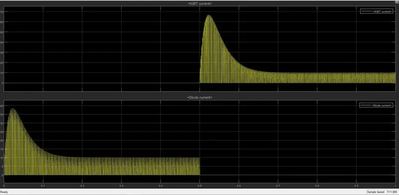
This plot shows currents flowing in the IGBT (Q3) and Diode (D3).
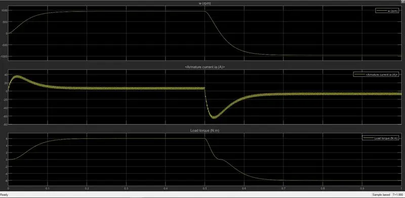
1B. Comment on the armature current shoot-up from the scope results.
At the beginning we can observe (refer the above plot) that there is rise in the armature current when the pulse width is 75%.
Wkt
Ia = V – Eb / Ra
At the starting point back emf (Eb) and speed will be zero (0).
So, Ra (Armature Resistance) will be very less which will increase the Ia (Armature Current).
If we decrease the pulse width (%) in the pulse generator block, there will be decrease in the voltage applied across the DC Motor and finally, the armature current will decrease and vice-versa.
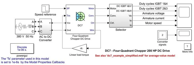
1C. Refer to the help section of ‘The Four-Quadrant Chopper DC Drive (DC7) block’. Compare it with the H-bridge model.
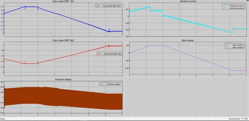
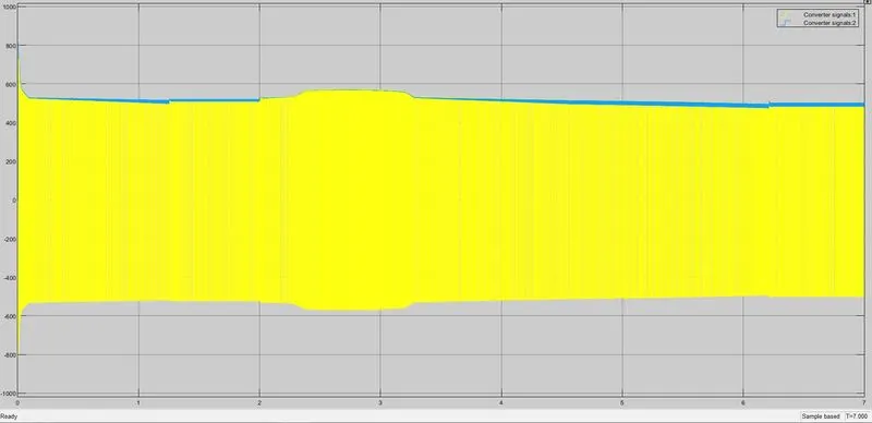
Reference of Four-quadrant chopper
|
H-Bridge |
Four Quadrant Chopper |
|
Here we need to change the polarity to change the motion (forward or backward) |
Here we need to interrupt the signals to another |
|
Regenerative braking is not possible |
Regenerative braking is possible |
|
Simulation will be Continuous |
Simulation will be Discrete |
|
Takes more time to simulate |
Comparatively, takes less time to simulate |
|
Efficiency will be less compared to four quadrant choppers |
Efficiency will be more compared to H-Bridge |
2. Develop a 2-quadrant chopper using Simulink & explain the working of the same with the relevant results. (Refer to article – multi-quadrant operation of motor)
Two-Quadrant copper is also called as class-C chopper. It only functions in 1st and 2nd quadrants, output voltage is always positive and the output current can be positive (1st quadrant) or negative (2nd quadrant).
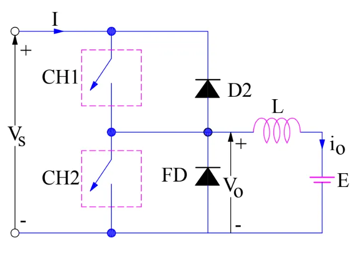
1st quadrant will work when CH1 or FD is ON and 2nd quadrant will work when CH2 or D2 is ON. We should not turn ON CH1 and CH2 simultaneously, because the DC supply will get short circuit.
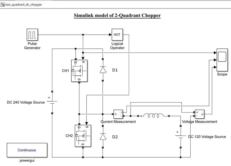
Given input DC voltage source of 240V, here we have used MOSFET for switching purpose, Measurement’s block to measure the current and voltage across the points, diodes, logical operator (NOT), pulse generator, powergui, inductor and scope blocks.
Here pulse generated signals are given to the port-g in CH1 block, by connecting to the Logical operator (NOT), other port of NOT block is connected to the port-g in CH2 block, this NOT block takes care to do not operate the switches simultaneously (for example: if the CH1 is ON then CH2 will be OFF and vice-versa). Inductor acts as a load here.
The simulation is run for 1second with Amplitude of 5, time period of 0.03 seconds and Pulse width of 50%.
1st Quadrant working
When the CH1 is ON the current flows asper the connections and charges the inductor with polarity (+ and –) so, the voltage and current are positive.
When the CH is OFF the inductor changes its polarity from (+ and –) to (- and +) where current flows from Battery to D2 (ON position) to inductor here discharging of the inductor takes place. So, the voltage and current are positive.
2st Quadrant working
When the CH2 is ON the current flows from ‘E’ to inductor and CH2 so, the inductor will get charged (stored energy) with (+ and -) polarity. so, the voltage is positive and current are negative.
When the CH2 is turned OFF, the inductor will release the stored energy via D1 (ON position) so, the voltage is positive and current are negative.
Results:
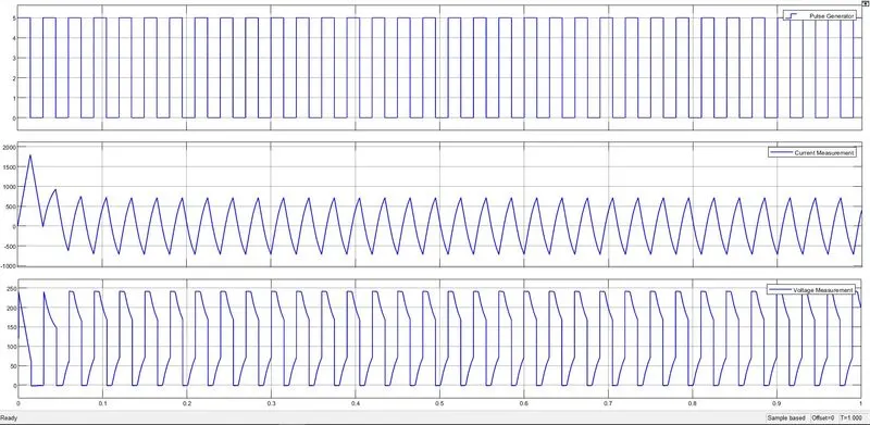
We can observe that Voltage is positive in both the quadrants were as Current is positive in 1st quadrant (CH1 and D2) and negative in 2nd quadrant (CH2 and D1).
3. Explain in a brief about operation of BLDC motor.
Complete Explanation of BLDC Motor
Introduction
Brushless DC Motor have become a significant contributor of the modern drive technology. Their rapid gain in popularity has seen an increasing range of applications in the field of Consumer applications, Automotive Industry, Industrial Automation, Chemical and Medical, Aerospace and Instrumentation.
Even though they have been used for drivers and power generation for a long time, thr sub kilowatt range, which ahs been dominated by Brushed DC Motors, has always been a grey area. But the modern power electronics has allowed the small Brushless DC Motors to thrive, both in terms of price and performance.
What is a BLDC Motor?
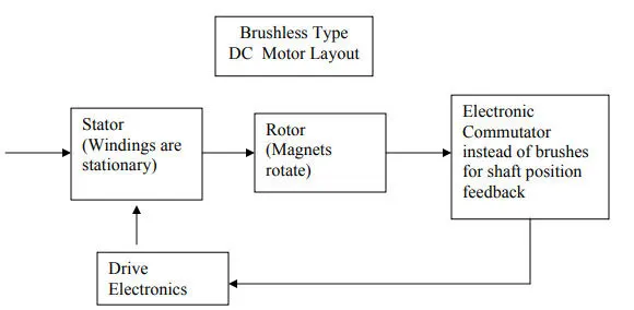
A Brushless DC Motor is similar to a Brushed DC Motor but as the name suggests, a BLDC doesn’t use brushes for commutation but rather they are electronically commutated. In conventional Brushed DC Motors, the brushes are used to transmit the power to the rotor as they turn in a fixed magnetic field.
As mentioned earlier, a BLDC motor used electronic commutation and thus eliminates the mechanically turn brushes.
Construction of BLDC Motor
The main design difference between a brushed and brushless motors is the replacement of mechanical commutator with an electric switch circuit. Keeping that in mind, a BLDC Motor is a type of synchronous motor in the sense that the magnetic field generated by the stator and the rotor revolve at the same frequency.
Brushless Motors are available in three configurations: single phase, two phase and three phase. Out of these, the three phase BLDC is the most common one.
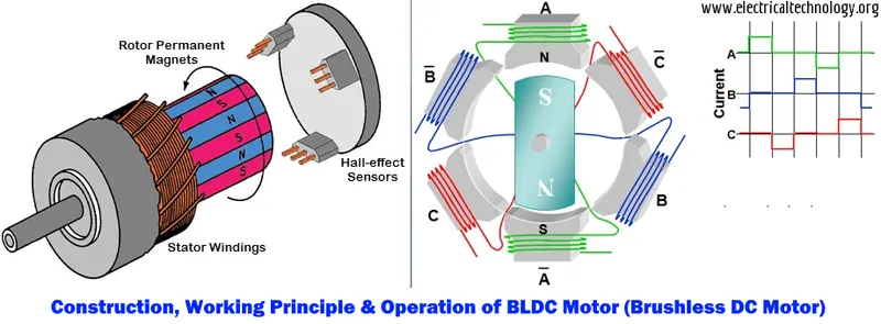
As you can see in the image, a BLDC Motor consists of three main parts: stator, rotor and hall-sensor.
Stator
The structure of the stator of a BLDC Motor is similar to that of an induction motor. It is made up of stacked steel laminations with axially cut slots for winding. The winding in BLDC is slightly different than that of the traditional induction motor.
Generally, most BLDC motors consists of three stator windings that are connected in star or ‘Y’ fashion (without a neutral point). Additionally, based on the coil interconnections, the stator windings are further divided into Trapezoidal and Sinusoidal Motors.
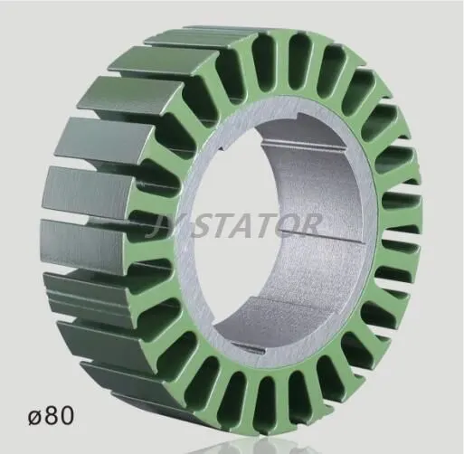
In a trapezoidal motor, both the drive current and the back EMF are in the shape of a trapezoid (sinusoidal shape in case of sinusoidal motors). Usually, 48 V (or less) rated motors are used in automotive and robotics (hybrid cars and robotic arms).
Rotor
The rotor part of the BLDC Motor is made up of permanent magnets (usually, rare earth alloy magnets like Neodymium (Nd), Samarium Cobalt (SmCo) and alloy of Neodymium, Ferrite and Boron (NdFeB)).
Based on the application, the number of poles can vary between two and eight with North (N) and South (S) poles placed alternately. There are three different arrangements of the poles. In the first case, the magnets are placed on the outer periphery of the rotor.
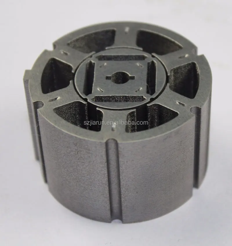
The second configuration is called magnetic-embedded rotor, where rectangular permanent magnets are embedded into the core of the rotor. In the third case, the magnets are inserted into the iron core of the rotor.
Position Sensors (Hall Sensors)
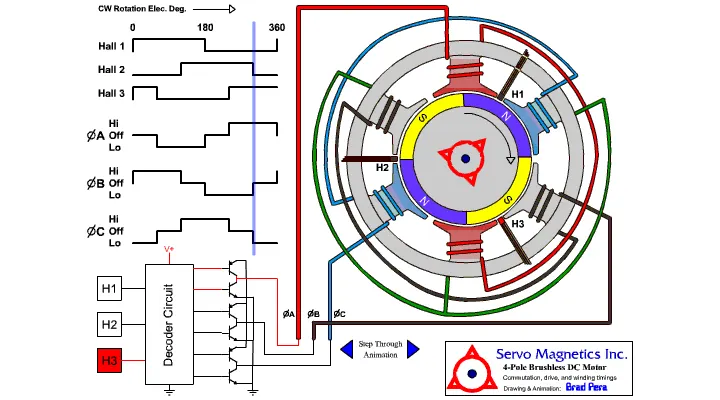
Since there are no brushes in a BLDC Motor, the commutation is controlled electronically. In order to rotate the motor, the windings of the stator must be energized in a sequence and the position of the rotor (i.e., the North and South poles of the rotor) must be known to precisely energize a particular set of stator windings.
A Position Sensor, which is usually a Hall Sensor (that works on the principle of Hall Effect) is generally used to detect the position of the rotor and transform it into an electrical signal. Most BLDC Motors use three Hall Sensors that are embedded into the stator to sense the rotor’s position.
The output of the Hall Sensor will be either HIGH or LOW depending on whether the North or South pole of the rotor passes near it. By combining the results from the three sensors, the exact sequence of energizing can be determined.
Working Principle and Operation of BLDC Motor
BLDC motor works on the principle similar to that of a conventional DC motor, i.e., the Lorentz force law which states that whenever a current carrying conductor placed in a magnetic field it experiences a force. As a consequence of reaction force, the magnet will experience an equal and opposite force. In case BLDC motor, the current carrying conductor is stationary while the permanent magnet moves.
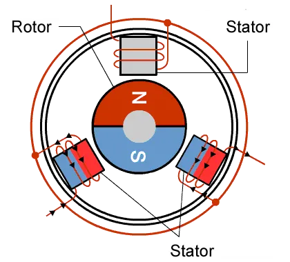
When the stator coils are electrically switched by a supply source, it becomes electromagnet and starts producing the uniform field in the air gap. Though the source of supply is DC, switching makes to generate an AC voltage waveform with trapezoidal shape. Due to the force of interaction between electromagnet stator and permanent magnet rotor, the rotor continues to rotate.
Consider the figure below in which motor stator is excited based on different switching states. With the switching of windings as High and Low signals, corresponding winding energized as North and South poles. The permanent magnet rotor with North and South poles aligns with stator poles causing motor to rotate.
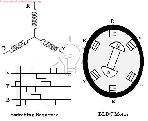
Observe that motor produces torque because of the development of attraction forces (when North-South or South-North alignment) and repulsion forces (when North-North or South-South alignment). By this way motor moves in a clockwise direction.
Advantages of BLDC Motor
- No wear and tear (due to absence of brushes)
- High efficiency
- Better speed vs torque characteristics
- Long life
- Less noise or noiseless operation
- Significantly higher RPM
Limitations
- These motors are costly
- Electronic controller required control this motor is expensive
- Requires complex drive circuitry
- Need of additional sensors
Applications of Brushless DC Motors
- Single speed applications
- Adjustable speed applications
- Position control
- Low noise applications
- High speed applications
- Computer hard drives and DVD/CD players
- Electric vehicles, hybrid vehicles, and electric bicycles
- Industrial robots, CNC machine tools, and simple belt driven systems
- Washing machines, compressors and dryers
- Fans, pumps and blowers.
CONCLUSION:
Hence, we have controlled the DC Motor as per the given conditions
- Explanation of the model ‘Speed control of a DC motor using BJT H-bridge’ have been completed and observed the Armature current results.
- Comparison of ‘Four quadrant chopper DC drive block’ with H-bridge model is done.
- We have created the Two quadrant chopper using Simulink and explained the working process as per the Simulink model.
- Briefly explained the construction and working principle of the BLDC Motor.
REFERENCE:
https://www.electronicshub.org/brushless-dc-motor-bldc-motor/