Week -2
- Build a Simulink model of Doorbell using solenoid block.
- Use a thermistor to sense the temperature to sense the temperature of a heater and turn on or turn off the fan.
- Build a Simulink model of Doorbell using solenoid block.
AIM:
To build a Simulink model of a Doorbell using Solenoid Simulink block.
OBJECTIVES:
- Create a situation where the switch is closed for 2 seconds and then released.
- Observe the physical movement of the plunger.
THEORY:
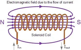
Solenoid is a type of electromagnetic, which generates a controlled magnetic field through a coil wounded in to a tightly packed helix. The coil can be arranged to produce a uniform magnetic field in a volume of space when an electric current is passed through it.
SIMULINK MODEL OF DOORBELL USING SOLENOID BLOCK:
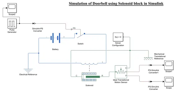
Blocks used for building Doorbell simulation
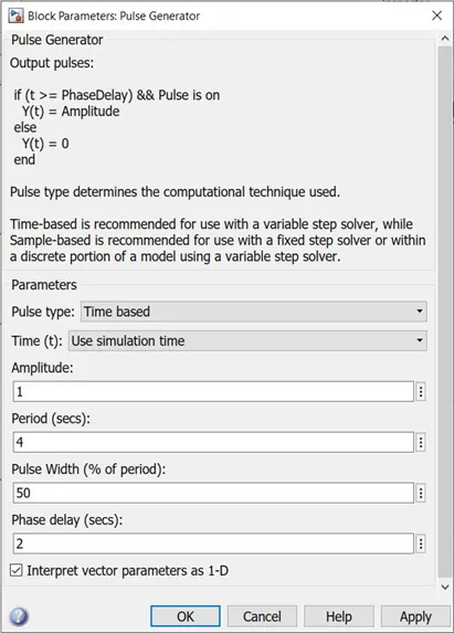
Pulse Generator – It generates square wave pulses at regular intervals.
if (t >= PhaseDelay) && Pulse is on
Y(t) = Amplitude
else
Y(t) = 0
end
Time-based is recommended for use with a variable step solver.
Sample-based is recommended for use with a fixed step solver or within a discrete portion of a model using a variable step solver.
Input
Simulink to PS converter - Converts the Simulink input signal to a Physical Signal.
Switch - The block represents a switch controlled by an external physical signal. If the external physical signal PS is greater than the threshold, then the switch is closed, otherwise the switch is open.
Battery - This block models a simple battery setup.
Electrical reference - Electrical reference block represents an electrical ground connection. Any model with electrical elements must contain at least one Electrical Reference block.
Solenoid - It implements the electrical and mechanical characteristics of a solenoid. The plunger Maximum stroke is implemented as a hard stop, the dynamics of which are set by the Contact stiffness and Contact damping parameters. The same parameters are used to model the contact dynamics when the plunger pulls fully in. The Spring constant parameter is used to implement a spring force that pulls the plunger out, and can be set to zero.
Mechanical reference - This block represents a mechanical translational reference point, that is, a frame or a ground. Use it to connect mechanical translational ports that are rigidly affixed to the frame (ground).
Solver Configuration – It automatically defines solver settings to use for simulation.
Ideal Translational Motion Sensor - This block measures velocity or displacement in a mechanical translational network. The sensor is ideal since it does not account for inertia, friction, delays and energy consumption etc.
PS to Simulink converter - Converts the input Physical Signal to a Simulink output signal.
Scope - It display signals generated during simulation.
LAYOUT EXPLANATION WITH OUTPUT PLOTS:
- Initially required Simulink block like Pulse Generator, Simulink to PS converter, Switch, Battery, Electrical reference, Solenoid, Mechanical reference, Solver Configuration, Ideal, Translational Motion Sensor, PS to Simulink converter and Scope have been imported in to the Simulink canvas.
- In the pulse generator, time-based pulse type is selected. To close the switch for 2 seconds and then release, Period (secs) set to ‘4’, Time delay (secs) is set to ‘2’. Pulse width (in % to period) set to 50.
- Additionally, scope2 block is created to plot the given data in pulse generator as input signals.
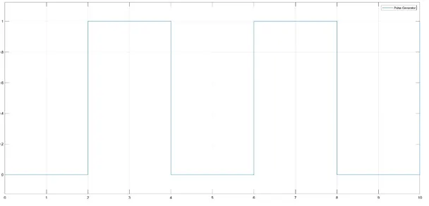
From the plot we can observe that for every 2 seconds the pulse is generated means the switch is close for 2 seconds and then released.
- The given signals from the pulse generator are send to the switch via a converter, where it converts the input signal from the Simulink to physical signal to the switch.
- One end of the switch is connected to the ‘+’ side of the battery and the other end is connected to ‘+’ side of the solenoid.
- ‘-‘ side of the battery is connected to the ‘-‘ side of the solenoid and additional connection is made to the ground (electrical references).
- R and C are the mechanical conserving in the solenoid block, where R (Plunger) is connected to the Rod (R) – positive probe of the Ideal Translational Motion Sensor block and C (case) is connected to mechanical translational reference.
- In the Ideal Translational Motion Sensor block P and V points are the outputs which will result the position and velocity of the plunge and these ports are connected to scope via Ps to Simulink converter.
- Port C is connected to case (reference probe) is connected to mechanical translational reference and additionally solver configuration block is added.
- After running, the output plots will be in the scope block.
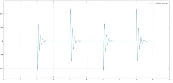
Velocity of the Plunger
Position of the Plunger
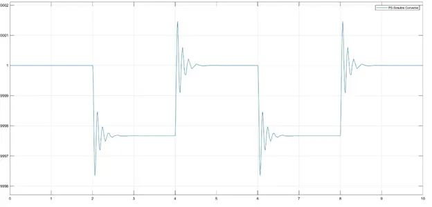
From the velocity and position of the plunger plots we can conclude that the bell is rung for every 2 seconds, when the simulation was run for 10 seconds.
Conclusion:
By giving the input signal in the pulse generator the switch is opened and closed with the time interval of 2 seconds. When the switch is closed, solenoid will block the electric current from the battery and plunger will move from port R to C which will hit the bell and sound will be generated. The physical movement of the plunger is observed by translational motion sensor. To reduce the vibrations, we have to reduce the spring constant value and increase the damping value.
2. Use a thermistor to sense the temperature of a heater and turn on or turn off the fan.
AIM:
To sense the temperature of a heater using thermistor block to turn on or turn off the fan.
OBJECTIVES:
- To provide temperature sources as per given conditions.
- Turn ‘on’ the fan if the temperature is above 25 degrees, otherwise turn off.
Input Condition
0 to 10 sec temp is 20 °C
10 to 30-sec temp is 27 °C
30 to 50-sec temp is 23 °C
Output condition
Fan should be turn ON if temperature is > 25 °C
Otherwise turn OFF
THEORY:
Thermistor is a semi-conductor that has a resistance capacity more than a conducting material and less than insulating material. Its electrical resistance varies with the change in the temperature or thermally sensitive resistor.
There are mainly two types of thermistors, namely
- Negative Temperature Coefficient (NTC)
- Positive Temperature Coefficient (PTC).
Thermistor’s relation with temperature also depends on the material in which it is made. A negative temperature coefficient (NTC) thermistor will decrease its resistance value when temperature increases whereas a Positive temperature coefficient will increase its resistance when temperature increases.
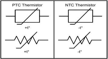
Thermistors have high sensitivity which can be up to 10 percent change per degree Celsius and their typical response time is 0.5 to 5s with an operating range from -50 to ~300 °C and there are devices with more capacity.
Simulink blocks used for building Heater simulation
signal Builder - Used to generate the signal according to the given input condition.
Input condition
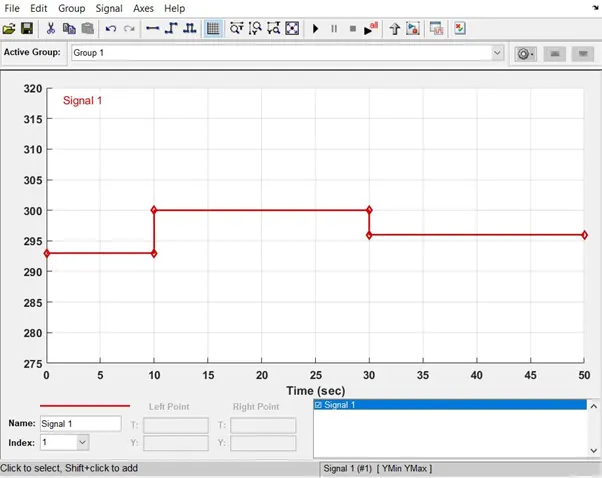
On X-axis Time (Sec) is indicated and on Y-axis Temperature (K) in indicated.
At state – 1: Time is 0 second and Temperature is 293 K.
At state – 2: Time is 10 seconds and Temperature is 293 K.
At state – 3: Time is 10 seconds and Temperature is 300 K.
At state – 4: Time is 30 seconds and Temperature is 300 K.
At state – 5: Time is 30 seconds and Temperature is 296 K.
At state – 6: Time is 50 seconds and Temperature is 296 K.
PS-Simulink converter - Converts Simulink signals to the respective physical signal.
Controlled temperature source: (CTS) Provide a temperature physical output based on the condition given to port S.
Thermal reference - Thermal reference block provides the required initial conditions to the connected thermal block for the solver.
Thermistor - Thermistor block which shows us the NTC thermistor relation between temperature and resistance.
Battery - Battery is a storage device that provides the required voltage based on the parameter given. We can use DC voltage source blocks too.
Resistor - Resistor which provides the opposing nature of current in a circuit.
Voltage sensor - This is used to measure the voltage or potential difference across any electrical component and it should connect in parallel only.
Electrical Reference - These domain-specific electrical reference blocks will provide the required initial conditions to the connected thermal block for the solver.
Solver Configuration - The Solver Configuration block specifies the solver parameters that your model needs before you can begin simulation and this is mandatory for all simscape designs.
PS-Simulink Converter - Converts physical signals to the respective Simulink signal.
Constant - Provides a constant output value.
Switch - This block is used from the library Simulink / Signal Routing where it has three inputs namely Port1, Port2, and Port3. Port2 is a control input where the signal given to port2 is satisfied with the condition and threshold of the switch block then it passes Port1 as output and if it is not satisfied then it will pass Port3 as output.
Scope - This is an output block that shows the signal with respective time in an X-axis.
LAYOUT EXPLANATION WITH OUTPUT PLOTS:
- First, import the all the required Simulink blocks (Thermal, electrical and general Simulink) in to the Simulink canvas.
- In the signal builder block given temperature ranges should be plotted in the form if graph. Then connect signal builder to thermistor ‘A’ using controlled temperature source ‘B’ and Simulink to PS convertor.
- Controlled temperature source ‘A’ point is connected to thermal reference by connecting solver configuration.
- Thermistor ‘+’ side and ‘- ‘ is connected to battery ‘+’ side and resister ‘+’ side. Battery ‘-‘ side is connected to resister ‘-‘ side along with electrical reference.
- Connect a resistor along with voltage source. Check the voltage across the resistor and note the respective voltage value for 25 °C.
- Voltage sensor of port ‘V’ is connected to the switch port (2) (controlled port) via PS to Simulink convertor.
- The other two ports (1 and 3) (Data ports) of a switch block are connected to the constant input block.
- Finally, the scope block is connected and the required output is achieved in the form of plot.
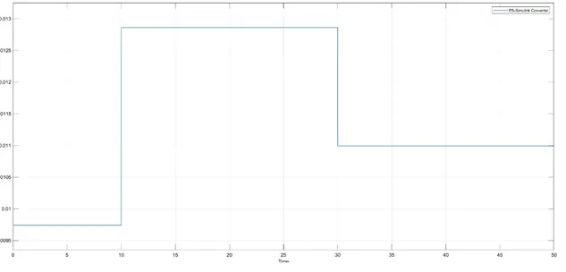
In the ‘Thermistor’ block the reference temperature (T0) is set default i.e., is 298.15K and Nominal resistance (R0) at reference temperature is 1000 ohm.
So, we can conclude that for 0-10 seconds fan is OFF where the temperature is 293K, which is below reference temperature (298.15K), for 10-30 seconds fan is ON where the temperature is 300K, which is above reference temperature (298.15K) and for 30-50 seconds fan is OFF where the temperature is 296K, which is below reference temperature (298.15K).
Conclusion:
Hence the required condition has been solved with the given proper inputs.
i.e.,
- Doorbell is rung for every 2 seconds for a time period of 10 seconds.
- Heater fan will turn ON when the temperature is above 25 degrees and otherwise turn OFF.