Week-7 Challenge: DC Motor Control
Theory:
DC Motor:
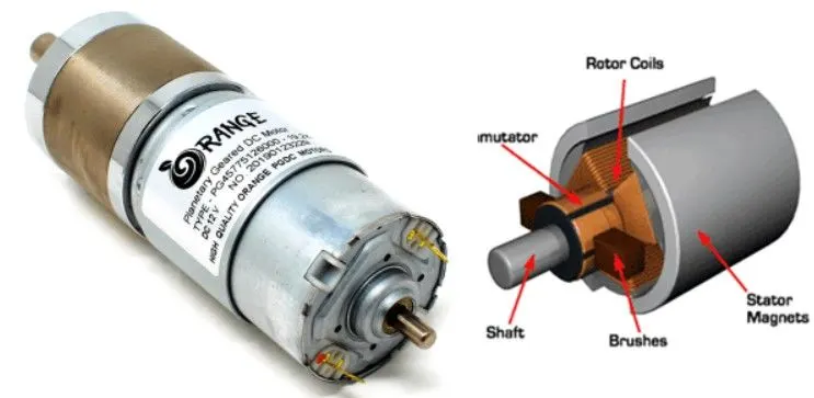
The DC Motor is the motor that converts the direct current into mechanical work. It works on the principle of Lorentz Law, which states that the current-carrying conductor placed in a magnetic and electric field experience a force. The most common types rely on the forces produced by magnetic fields. Nearly all types of DC motors have some internal mechanism, either electromechanical or electronic, to periodically change the direction of current in a part of the motor.
A DC motor's speed and torque characteristics vary according to three different magnetization sources, separately excited field, self-excited field, or permanent field, which are used selectively to control the motor over the mechanical load's range. Self-excited field motors can be series, shunt, or a compound wound connected to the armature.
Speed Control of DC Motor:
Speed Control of DC motor manually or through an automatic control device. This is different from speed regulation – where the speed can regulate against the natural change in speed due to a change in the load on the shaft.
The speed of a DC motor (N) is equal to N = K (V – IaRa)/ ø Where K is a constant.
This implies three things:
- The speed of the motor is directly proportional to the supply voltage.
- The Speed of the motor is inversely proportional to armature voltage drop.
- The motor speed is inversely proportional to the flux due to the field findings
Thus, the speed of a DC motor can control in three ways:
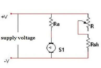
- By varying the flux, and by varying the current through the field winding
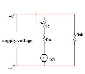
- By varying the armature voltage, and the armature resistance
- Through the supply voltage
Flux Control Method:
- Due to the field winding, the magnetic flux varies to vary the speed of the motor. As the magnetic flux depends on the current flowing through the field winding, it changes by varying the current through the field winding. This can achieve using a variable resistor in a series with the field winding resistor.
- Initially, when the variable resistor keeps at its minimum position, the rated current flows through the field winding due to a rated supply voltage, and as a result, the speed is kept normal. When the resistance increases gradually, the current through the field winding decreases. This in turn decreases the flux produced. Thus, the speed of the motor increases beyond its normal value.
Armature Control Method
- The controlling of armature resistance controls the voltage drop across the armature. With this method, the speed of the DC motor can control. This method also uses a variable resistor in series with the armature.
- When the variable resistor reaches its minimum value, the armature resistance is at a normal one. Therefore, the armature voltage drops. When the resistance value gradually increases, the voltage across the armature decreases. This in turn leads to a decrease in the speed of the motor. In this way, this method achieves the speed of the motor below its normal range.
Voltage Control Method:
- Both the above-mentioned methods cannot provide speed control in the desirable range. Moreover, the flux control method can affect commutation. Whereas the armature control method involves huge power loss due to its usage of the resistor in series with the armature. Therefore, a different method is often desirable – the one that controls the supply voltage to control the motor speed.
- In such a method, the field winding receives a fixed voltage, and the armature gets a variable voltage. One such technique of voltage control method involves the use of a switchgear mechanism to provide a variable voltage to the armature. Another one uses an AC motor-driven Generator to provide variable voltage to the armature (named as Ward-Leonard System).
Pulse Width Modulation :
- Apart from these, the most widely used technique is the use of pulse width modulation to achieve speed control of a DC motor. PWM involves the application of varying widths of pulses to the motor driver to control the voltage applied to the motor. This method proves to be very efficient as the power loss keeps at a minimum, and it doesn’t involve the use of any complex equipment.
- PWM is achieved by varying the pulses applied to the enable pin of the motor driver IC to control the applied voltage of the motor. The variation of pulses is done by the microcontroller, with the input signal from the pushbuttons. This type of operation is called switching and is achieved using Transistors. Some of the most widely used transistors are;
- IGBT – Insulated Gate Bipolar Transistor
- MOSFET– Metal Oxide Semiconductor Field Effect Transistor
- BJT– Bipolar Junction Transistor
- IGBT – Insulated Gate Bipolar Transistor:
It is a bipolar transistor with an insulated gate terminal. The IGBT combines, in a single device, a control input with a MOS structure and a bipolar power transistor that acts as an output switch. IGBTs are suitable for high-voltage, high-current applications. They are designed to drive high-power applications with a low-power input.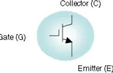
- MOSFET– Metal Oxide Silicon Field Effect Transistor:
This is also called IGFET meaning Insulated Gate Field Effect Transistor. The FET is operated in both depletion and enhancement modes of operation.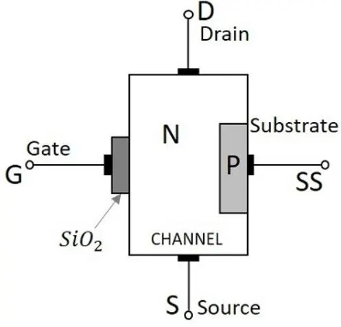
- BJT– Bipolar Junction Transistor:
It is a current-controlled electronic device main employed for amplification and switching purpose. It comes with three terminals called emitter, base, and collector. The small current at the base side is used to control the large current at the remaining terminals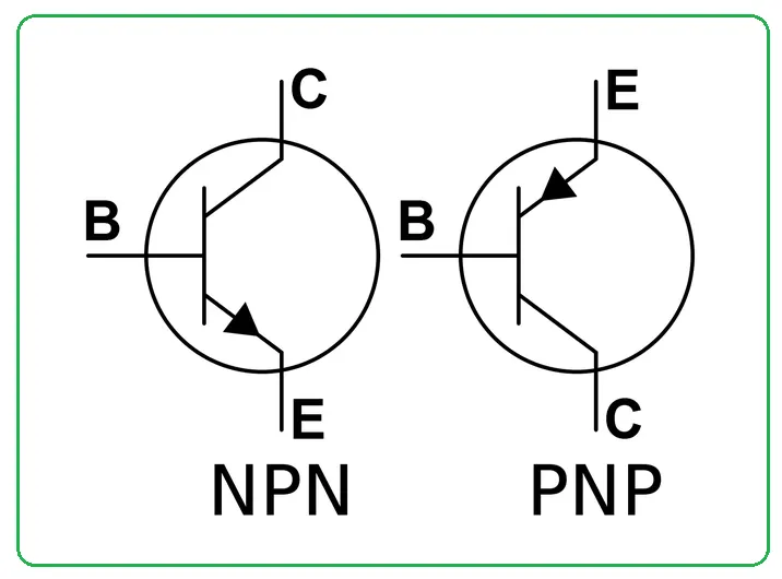
H -Bridge:
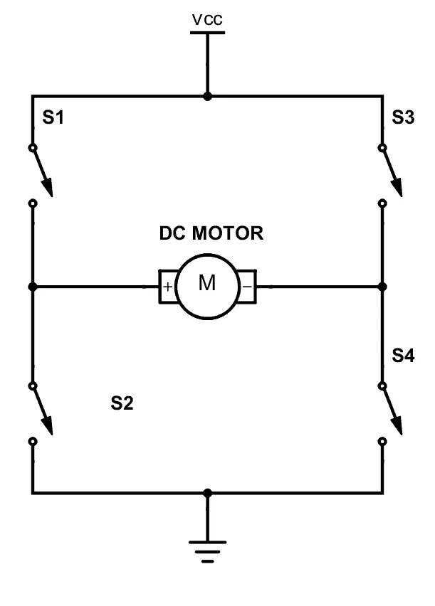
- An H-bridge is an electronic circuit that switches the polarity of a voltage applied to a load. These circuits are often used in robotics and other applications to allow DC motors to run forwards or backward.
- Most DC-to-AC converters (power inverters), most AC/AC converters, the DC-to-DC push-pull converter, isolated DC-to-DC converter.
- Most motor controllers and many other kinds of power electronics use H bridges.
- A bipolar stepper motor is almost always driven by a motor controller containing two H bridges.
- (a&b) Explain the MATLAB demo model named ‘Speed control of a DC motor using BJT H-bridge’ and Comment on the armature current shoot-up from the scope results.
MATLAB Model: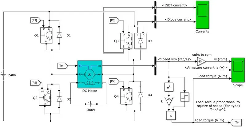
Pulse Generator: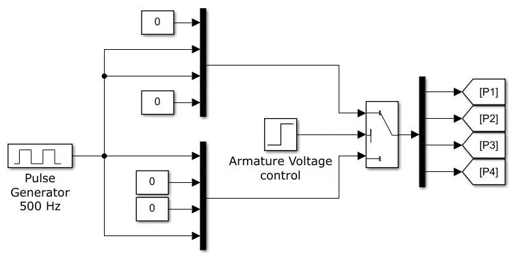
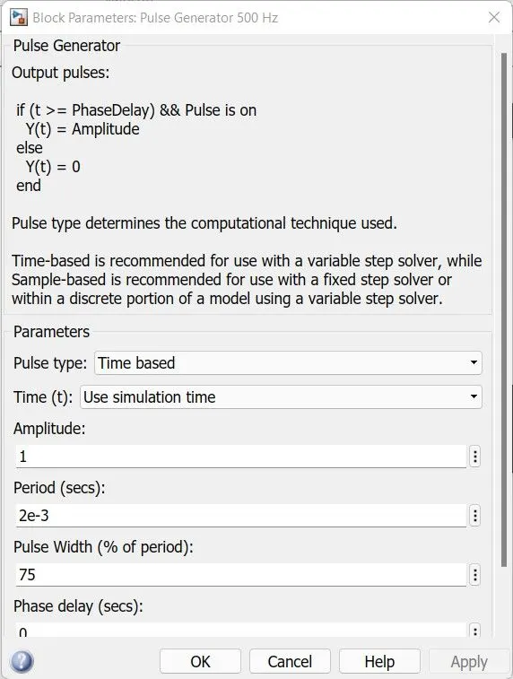
Components:
- DC Motor: A 5 HP, 240V, 1750 RPM, wound field motor is selected with a Field voltage of 300V
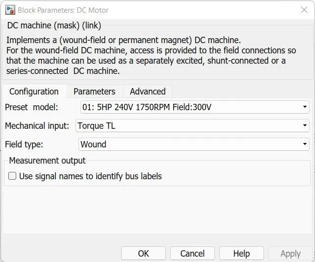
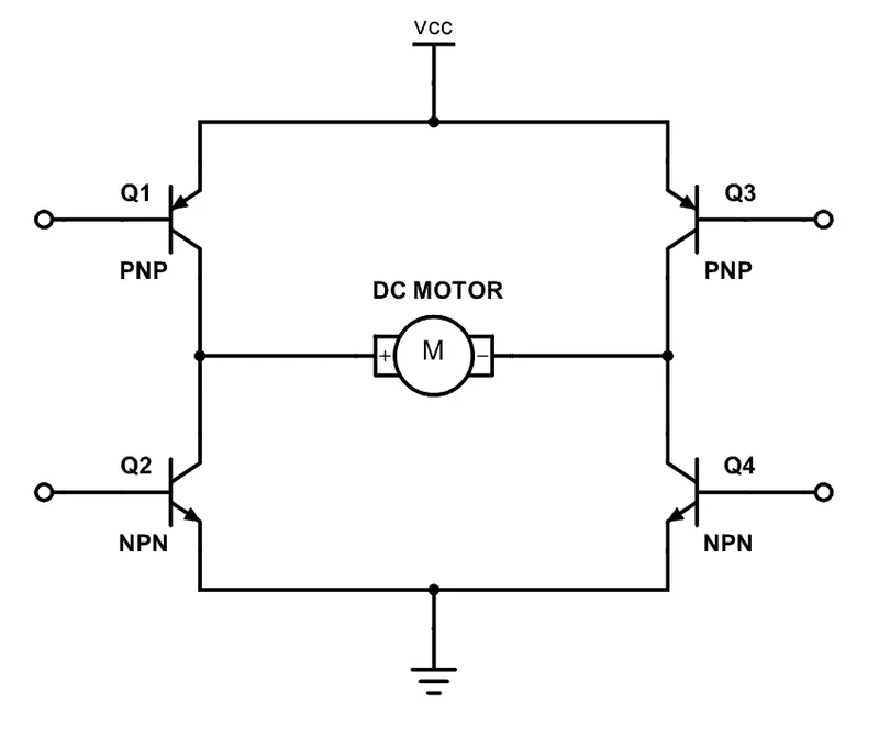
- IGBT: A total of 4 IGBT’s are provided for switching named as Q1, Q2, Q3, and Q4 connected in H - model
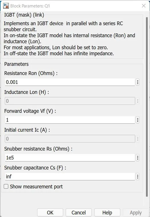
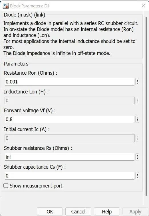
- Diode: each Diode namely, D1, D2, D3, and D4 are connected to IGBT in parallel respectively
Working:
The transistor can be operated as a switch, we will be able to make the motor spin in either direction by turning on and off the four transistors.
the DC motor spins either backward or forward, depending on how the polarity is.
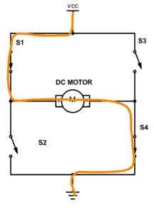
Case I:
When switches 1 and 4 are closed, you have plus connected to the left side of the motor and minus to the other side. And the motor will start spinning in one direction
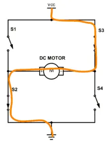
Case II:
If you instead close switch 2 and 3, you have plus connected to the right side and minus to the left side. And the motor spins in the opposite direction
a. Default Case:
The input parameter, which is the Pulse Generator is provided with,Amplitude = 1, Period = 2e-3 and Pulse width or Duty Cycle = 75%
b. Comment on the armature current shoot-up
The result obtained is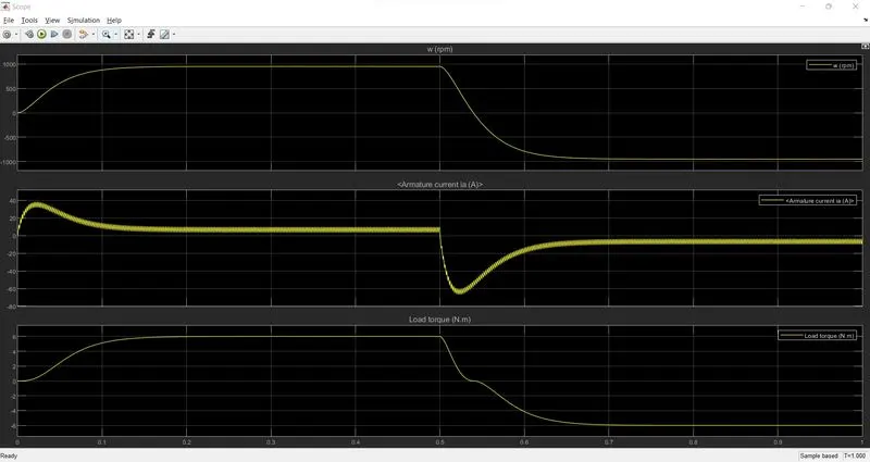
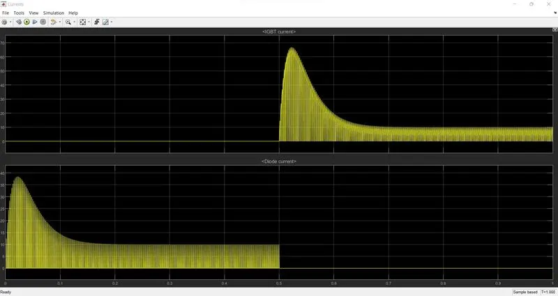
The Armature Current Shoot-up can be controlled by controlling the input parameters. Since the model is using the pulse generator, it is possible to vary the armature current by varying the duty cycle.
For a 100% Duty cycle, the armature current is spontaneously varying at High value
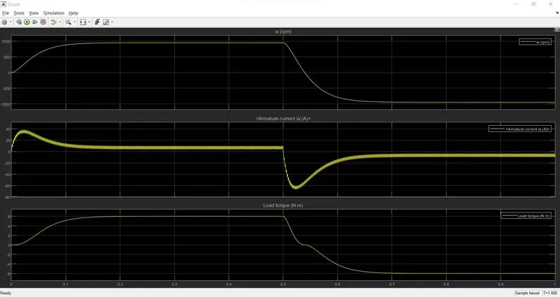
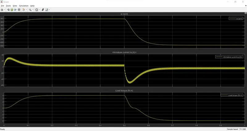
As we lower the duty cycle, the armature current also becomes stable
For 75% duty cycle,
For 70% duty cycle,
For 60% duty cycle,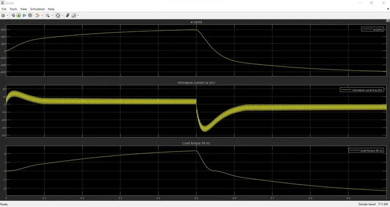
For 50% duty cycle,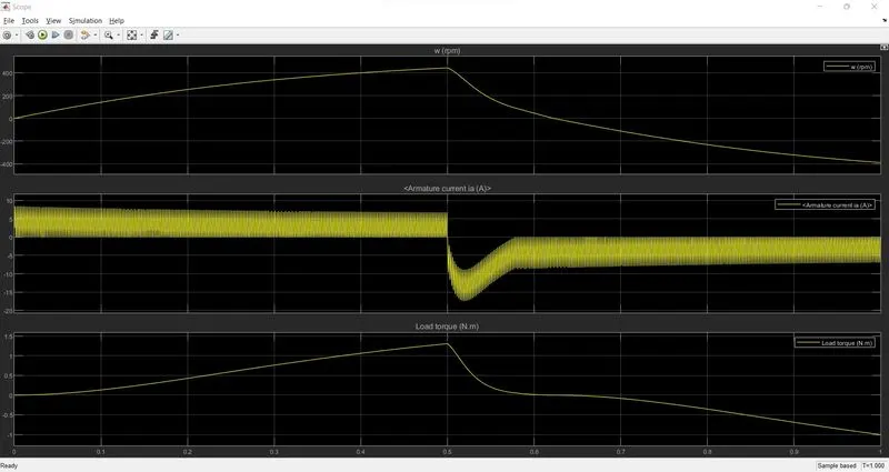
For 40% duty cycle,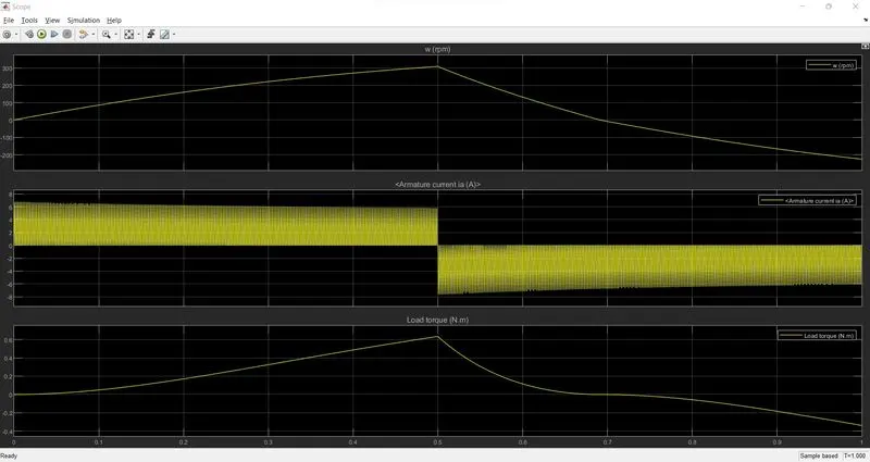
For 30% duty cycle,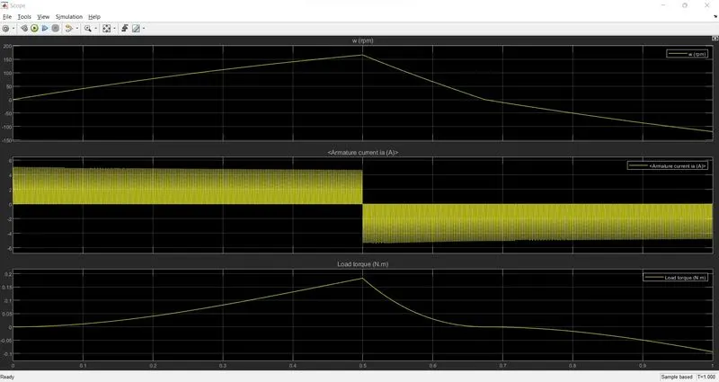
Result:
- The speed initially is made to shoot up quickly, which eventually leads to an overshoot above the set point.
- The speed is then brought down by adjusting the duty cycle and finally settles down around a duty cycle of 30-40%.
- It should be kept in mind that the P-D controller is not tuned
Conclusion:
- Based on the duty cycle the transient analysis carried out on the direct current dc series motor fed direct chopper has been
- Different types of parameters such as Armature current, Speed, and Load Torque are simulated and plotted.
- The performance of direct current dc motor fed direct chopper is compared with different duty cycles.
c. Refer to the help section of ‘The Four-Quadrant Chopper DC Drive (DC7) block’. Compare it with the H-bridge model.
Four Quadrant Operation of DC Motor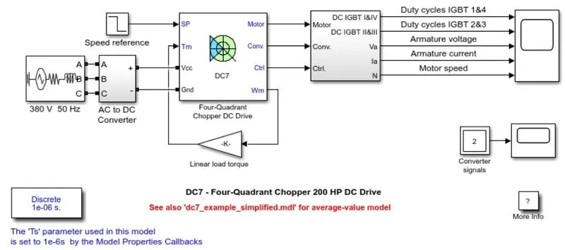
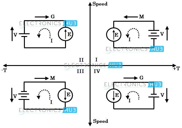
Four Quadrant Operation of any drives or DC Motor means that the machine operates in four quadrants. They are Forward Braking, Forward motoring, Reverse motoring, and Reverse braking.
- A motor operates in two modes –Motoring and Braking. A motor drive capable of operating in both directions of rotation and of producing both motoring and regeneration is called a Four Quadrant variable speed drive.
- In motoring mode, the machine works as a motor and converts the electrical energy into mechanical energy, supporting its motion. In braking mode, the machine works as a generator and converts mechanical energy into electrical energy and as a result, it opposes the motion. The Motor can work in both, forward and reverse directions, i.e., in motoring and braking operations.
- DC Motor: A 5 HP, 240V, 1750 RPM, wound field motor is selected with a Field voltage of 300V
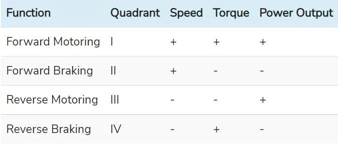
The product of angular speed and torque is equal to the power developed by a motor. For the multi-quadrant operation of drives, the following conventions about the signs of torque and speed are used. When the motor is rotated in the forward direction the speed of the motor is considered positive. For the drives which operate only in one direction, forward speed will be their normal speed.
In loads involving up and down motions, the speed of the motor which causes upward motion is in forwarding motion. For reversible drives, forward speed is chosen arbitrarily. The rotation in the opposite direction gives reverse speed which is denoted by a negative sign.
The rate of change of speed positively in the forward direction or the torque which provides acceleration is known as Positive motor torque. In the case of retardation, the motor torque is considered negative. Load torque is opposite to the positive motor torque in the direction.
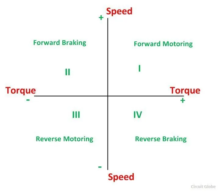
Quadrant I: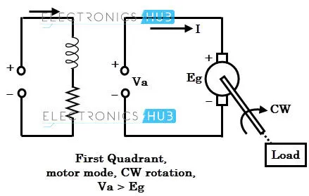
- In theFirst Quadrant, the power developed is positive and the machine is working as a motor supplying mechanical energy. The I (first) quadrant operation is called Forward Motoring.
- In this mode of operation, the applied voltage is positive and greater than the back emf of the motor, and therefore a positive current flows into the motor.
- Since both current and voltage are positive, the power becomes positive. And, the speed and torque are also positive in this quadrant. Therefore, the motor rotates in forward direction.
Quadrant II
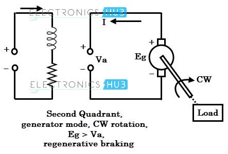
- In this mode of operation, the motor runs in the forward direction and the induced emf continues to be positive. But the supplied voltage is suddenly reduced to a value which is less than the back emf.
- This operation is also known as In this quadrant, the direction of rotation is positive, and the torque is negative, and thus, the machine operates as a generator developing a negative torque, which opposes the motion. The kinetic energy of the rotating parts is available as electrical energy which may be supplied back to the mains. In dynamic braking, the energy is dissipated in the resistance.
- Since the load torque and motor torque are in opposite directions, the combined effect will cause to reduce the speed of the motor, and hence back emf (motor emf is directly proportional to the speed) falls again below the applied voltage value.
- Hence, both current and voltage become positive, and the motor settles down to the first quadrant again. The process by which the mechanical energy of the motor is returned to the supply is called regenerative braking.
- This quadrant operation is an example of regenerative braking.
- Hence the current (thereby torque) will reverse direction. This negative torque reverses the direction of energy flow.
Quadrant III
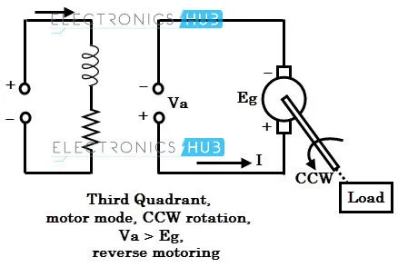
- The III (third) quadrant operation is known as reverse motoring.
- The motor works, in the reverse direction. Both the speed and the torque have negative values while the power is positive.
- Here, the motor in which both motor voltage and current are negative. Thus, the power is positive, i.e., the power is supplied from source to load.
- Due to the reverse polarity of the supply, the motor starts rotating in a counterclockwise direction (or reverse to normal operation).
- The operation of this quadrant is like the first quadrant, but the only difference is the direction of rotation. The magnitude of voltage to the motor decides the appropriate speed in the reverse direction.
Quadrant IV
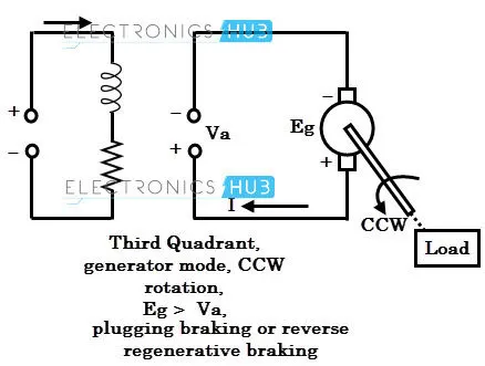
- This is the quadrant-4 mode of operation in which motor voltage is still negative and its armature current is positive.
- In the (fourth) quadrant, the torque is positive, and the speed is negative. This quadrant corresponds to the braking in the reverse motoring
- This mode of operation is like the second quadrant operation and once again the regeneration occurs whenever the back emf is more than the negative supply voltage.
- Hence the torque will be positive which opposes the load torque; thus, the speed of the motor will be reduced during reverse operation of the motor.
- This mode of operation is mostly used for plugging to stop the motor rapidly. During plugging, the armature terminals are suddenly reversed, which causes the back emf to force an armature current to flow in the reverse direction.
- Now the effective voltage across the motor becomes 2V (as V+ Eb). A braking resistor in series with the motor must be connected to limit this current.
- Braking by plugging gives greater torque and more rapid stop, but the current drawn from the supply and energy stored in mechanical parts must be dissipated in resistance.
Comparison between Four Quadrant Chopper DC Drive and BJT H- bridge Model
- In Four Quadrant Chopper DC Drive, Regenerative Braking is possible, which it’s not possible in BJT H- bridge Model
- In Four Quadrant Chopper DC Drive, there are a total of 4 modes – Forward Motoring, Forward Braking, Reverse Motoring and Reverse Braking, while In BJT H- bridge Model, there are only 2 modes – Forward and Reverse Motoring
- In Four Quadrant Chopper DC Drive, the direction of rotation of the motor is changed according to the input speed reference value, while in BJT H- bridge Model, the direction of rotation of the motor is changed by changing the polarity of the motor
- In Four Quadrant Chopper DC Drive, the motor is controlled by the speed reference value, while in BJT H- bridge Model, it is controlled using the duty cycle
- In Four Quadrant Chopper DC Drive, the overall performance and efficiency is much better compared to BJT H- bridge Model
- Develop a 2-quadrant chopper using Simulink & explain the working of the same with the relevant results. (Refer to the article - Multiquadrant operation of the motor )
Two Quadrant Chopper:
-
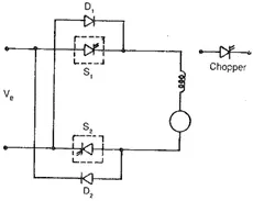
A chopper may be required to provide a two-quadrant operation by retaining the current direction in both motoring and braking modes. Such an arrangement Is called Two Quadrant Chopper. The chopper permits a change in the polarity of terminal voltage keeping the direction of current constant. Here, S1 and S2 are the choppers working as electronic switches and D1 and D2 are the feedback diodes. Assuming continuous conduction, both S1 and S2 operate simultaneously.
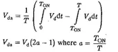
When they are ON, the load current Id increases, with the rate of rising depending upon the back emf and torque of the machine. When they are OFF, the load current is fed to the supply through the diodes D1 and D2. The current decreases in this stage. The load voltage is effectively negative when the diodes conduct. The average value of the output voltage of the chopper
-
Vda is zero for a = 0.5, the output voltage is an ac waveform with an average voltage equal to zero. For a > 0.5 the average value of the dc voltage is negative. The chopper works in the regeneration mode. The power flows from the load to the supply and the dc machine operates as a generator. For control ratios a c 0.5, the operation is like the inversion of a line commutated converter (α > 90°). For a > 0.5 the chopper has normal operation. The power flows from the supply to the load. This operation of the chopper is like the rectification of a line commutated converter (α < 90°). For, a = 0.5 the load voltage is zero.
MATLAB Simulink Model
RESULT: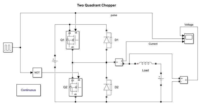
Components:
Pulse Generator: A Signal of Amplitude, 10 is generated with a duty cycle of 50%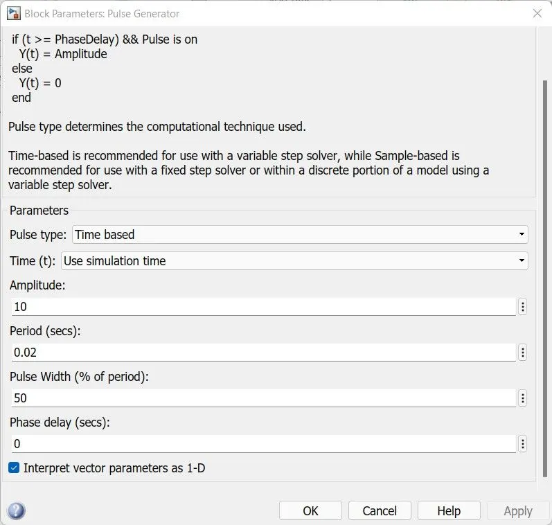
MOSFET: There are two MOSFETs, Q1 and Q2, where Q1 is operated in Forward Motoring while Q2 is operated during Reverse Motoring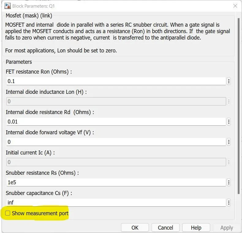
Diode: There are two diodes D1 and D2 connected parallelly with Q1 and Q2.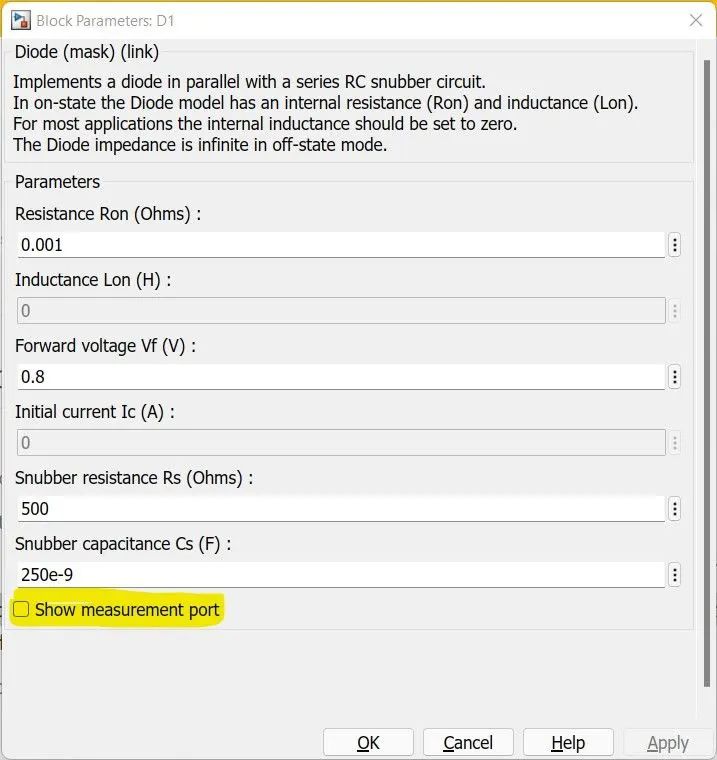
RLC Load: The RLC load mimics a load. In addition to the load, a DC Voltage of 12V is provided as a supply to the load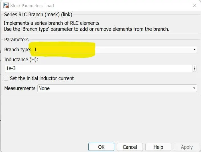
Logical Operator: An NOT logical gate is used to feed the signal accordingly to Q1 and Q2 from the Pulse generator. When high, a signal is fed to Q1 and when low, it is fed to Q2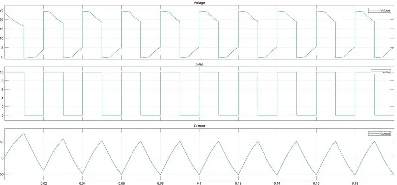
3. Explain in a brief the operation of the BLDC motor.
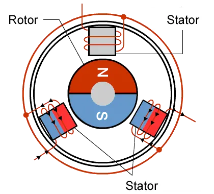
A brushless DC electric motor (BLDC motor or BL motor), also known as an electronically commutated motor (ECM or EC motor) or synchronous DC motor, is a synchronous motor using a direct current (DC) electric power supply. It uses an electronic closed-loop controller to switch DC currents to the motor windings producing magnetic fields which effectively rotate in space and which the permanent magnet rotor follows. The controller adjusts the phase and amplitude of the DC current pulses to control the speed and torque of the motor. This control system is an alternative to the mechanical commutator (brushes) used in many conventional electric motors
The construction of a brushless motor system is typically like a Permanent Magnet Synchronous Motor (PMSM), but can also be a Switched Reluctance Motor, or an Induction (Asynchronous) Motor.
They may also use neodymium magnets and be out-runners (the stator is surrounded by the rotor), in-runners (the rotor is surrounded by the stator), or axial (the rotor and stator are flat and parallel)
Construction of Brushless DC motor
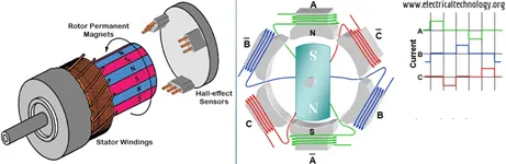
- In this motor, the permanent magnets are attached to the rotor. The current-carrying conductors or armature windings are located on the stator. They use electrical commutation to convert electrical energy into mechanical energy.
- The main design difference between brushed and brushless motors is the replacement of a mechanical commutator with an electric switch circuit. A BLDC Motor is a type of synchronous motor in the sense that the magnetic field generated by the stator and the rotor revolve at the same frequency.
- The Brushless motor does not have any current-carrying commutators. The field inside a brushless motor is switched through an amplifier which is triggered by the commutating device like an optical encoder.
- The layout of a DC brushless motor can vary depending on whether it is in “Outrunner” style or “In-runner” style.
- Outrunner –The field magnet is a drum rotor that rotates around the stator. This style is preferred for applications that require high torque and where high rpm isn’t a requirement.
- In runner– The stator is a fixed drum in which the field magnet rotates. This motor is known for producing less torque than the out-runner style but is capable of spinning at very high rpm.
Working Principle of Brushless DC motor
- BLDC motor works on the principle like that of a brushed DC motor.
- The Lorentz force law states that whenever a current-carrying conductor is placed in a magnetic field it experiences a force. Because of the reaction force, the magnet will experience an equal and opposite force.
- In the BLDC motor, the current-carrying conductor is stationary and the permanent magnet is moving.
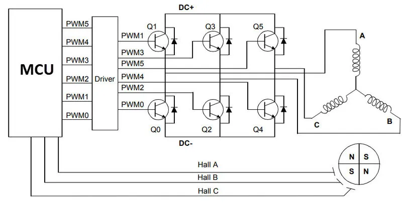
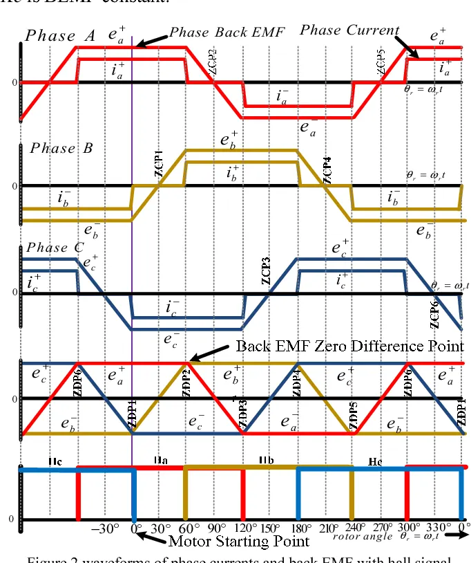
- When the stator coils get a supply from the source, it becomes an electromagnet and starts producing the uniform field in the air gap. Though the source of supply is DC, switching makes to generate an AC voltage waveform with a trapezoidal shape. Due to the force of interaction between the electromagnet stator and permanent magnet rotor, the rotor continues to rotate.
- With the switching of windings as High and Low signals, corresponding winding energized as North and South poles. The permanent magnet rotor with North and South poles aligns with stator poles which causes the motor to rotate.
- In brushless DC motors, an electronic servo system replaces the mechanical commutator contacts.
- An electronic sensor detects the angle of the rotor and controls semiconductor switches such as transistors which switch current through the windings, either reversing the direction of the current or, in some motors turning it off, at the correct angle so the electromagnets create torque in one direction. The elimination of the sliding contact allows brushless motors to have less friction and longer life; their working life is only limited by the lifetime of their bearings.
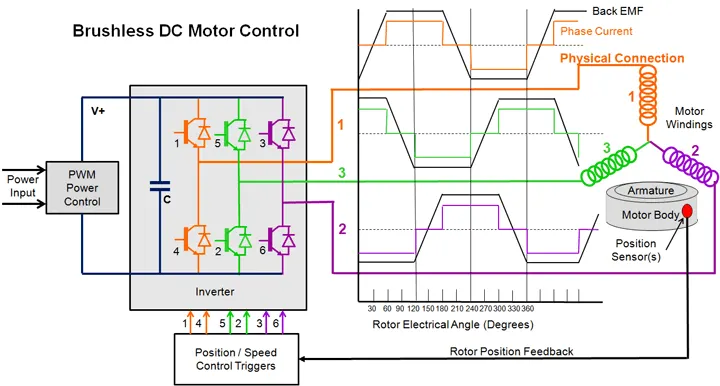
Four Quadrant torque ripple-free operation of BLDC Motor
Advantages of Brushless DC motor
- Less overall maintenance due to absence of brushes
- Reduced size with far superior thermal characteristics
- Higher speed range and lower electric noise generation.
- It has no mechanical commutator and associated problems
- High efficiency and high output power to size ratio due to the use of permanent magnet rotor
- Smaller motor geometry and lighter in weight than both brushed type DC and induction AC motors.
- Long-life as no inspection and maintenance is required for commutator system
- Higher dynamic response due to low inertia and carrying windings in the stator
- Less electromagnetic interference
- Low noise due to absence of brushes
- High speed of operation even in loaded and unloaded conditions due to the absence of brushes that limits the speed
Limitations of Brushless DC motor
- These motors are costly
- The electronic controller required to control this motor is expensive
- Requires complex drive circuitry
- Need of additional sensors
Application of Brushless DC motor
Brushless DC motors (BLDC) are used for a wide variety of application requirements such as varying loads, constant loads, and positioning applications in the fields of industrial control, automotive, aviation, automation systems, health care equipment, etc.
- Computer hard drives and DVD/CD players
- Electric vehicles, hybrid vehicles, and electric bicycles
- Industrial robots, CNC machine tools, and simple belt-driven systems
- Washing machines, compressors, and dryers
- Fans, pumps, and blowers.