Week-7 Challenge: DC Motor Control
1. A. Explain a MATLAB demo model named ‘Speed control of a DC motor using BJT H-bridge’.
B. Comment on the armature current shoot-up from the scope results.
C. Refer to the help section of ‘The Four-Quadrant Chopper DC Drive (DC7) block’. Compare it with the H-bridge model.
Sol
H bridge is a simple circuit which is used to control a dc motor in forward and backward direction,H bridge is a circuit consisting of 4 switching element as shown below i.e Q1,Q2,Q3,Q4.
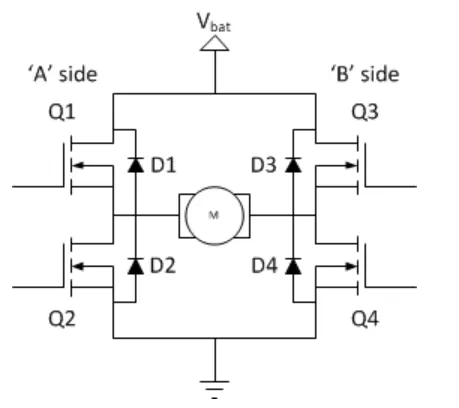
These switches are usually bi polar or FET,in some application we use IGBT and MOSFET as well.D1 to D4 are called Catch diodes and are usually Schottky type.
Top end is connected to the Battery supply and bottom end is grounded.
Working of H-Bridge model:
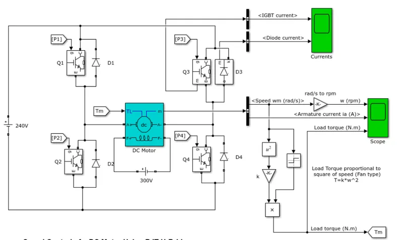
Here four switches are used with Pulses P1 P2 P3 P4
In first state Q1 and Q4 are closed by giving 1v to igbt,current from battery passes from Q1 and Q4,diode D2 D3 are used as free wheeling diode,In this case Forward motoring and Forward breaking Happens.
In second state Q2 and Q3 are closed ,D1 D4 are used as free wheeling diode ,Hence motor works in reverse motoring and reverse breaking.
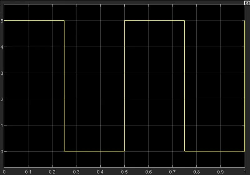
Both the states are occuring at 0.5s in their sample time.
in motor operation armature terminals are connected with a 240v and field windings are connected to 300V dc supply to act as an electromagnet.
load torque is given as mechanical input to the motor through this magnetic field is generated variable current carrying conductor in rotor armature produces force.thus motor starts to rotate.
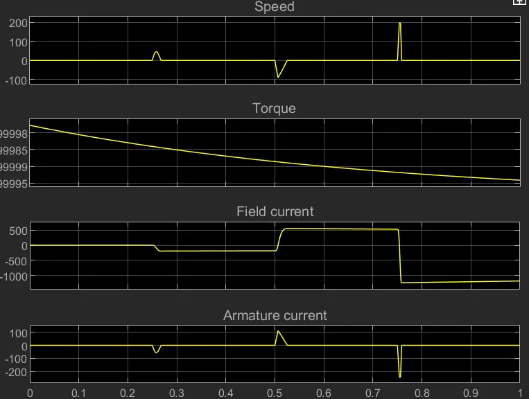
from the result
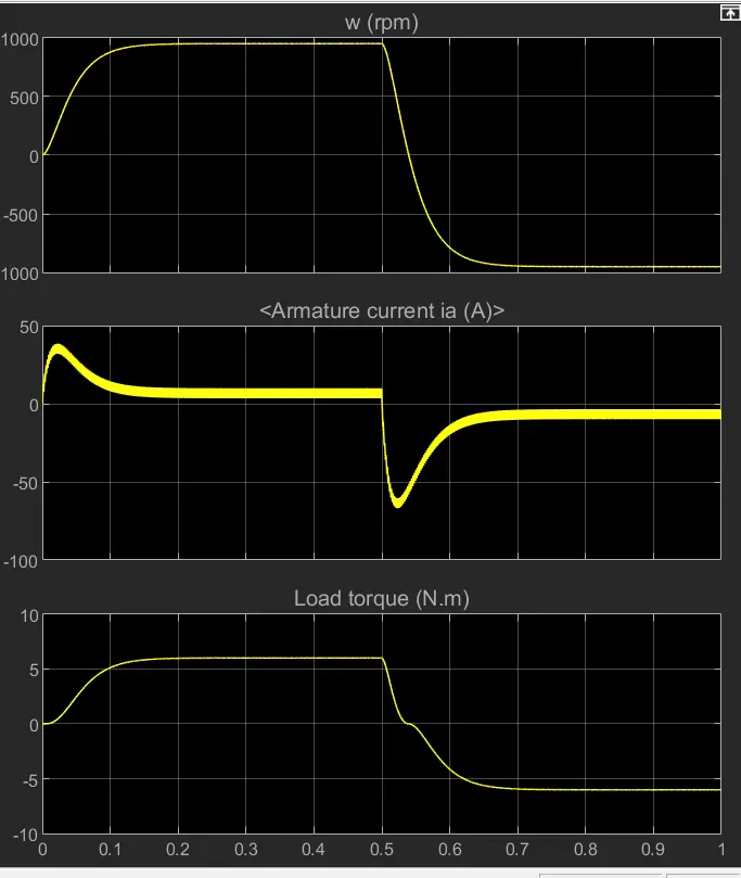
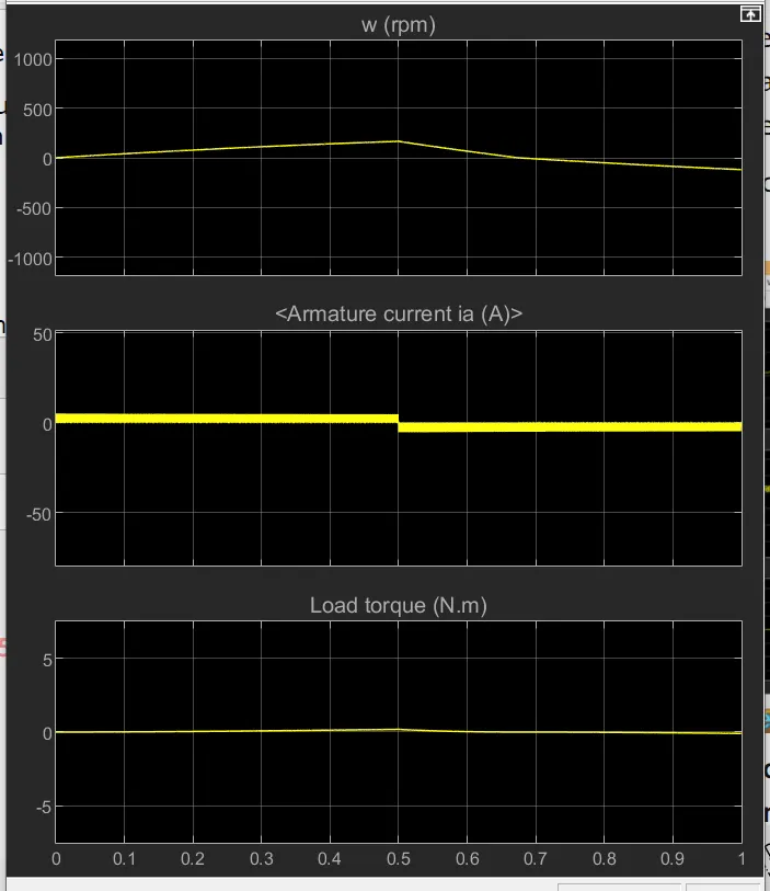
speed of motor initially increases to 900rpm upto 0.5s during forward motoring
then it reduces to 0rpm due to forward dynamic breaking
then it increases from 0-=900rpm upto 1sec that is at reverse motoring and then reverse braking occurs.
2
Similarly Load torque increases in forward motoring and reverse motoring and decreases in breaking
B. Comment on the armature current shoot-up from the scope results.
Due to the increase in voltage their is a sudden increase in current which is regulated by duty cycle.
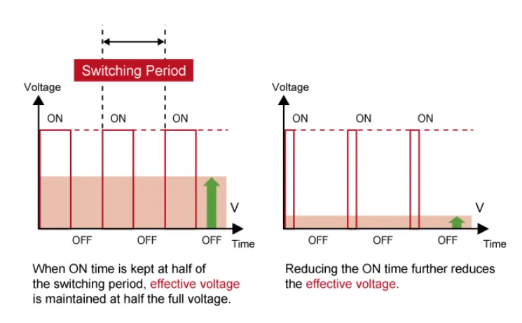
Here it is 75% duty cycle which means 0.75* 240=180V
But if we decrease the duty cycle by 30% ,the shoot up of current get decreased on both positive and negative side.
Conclusion :
to reduce the shootup of armature current we have to change the duty cycle that inturn increases voltage and speed.
C. Refer to the help section of ‘The Four-Quadrant Chopper DC Drive (DC7) block’. Compare it with the H-bridge model
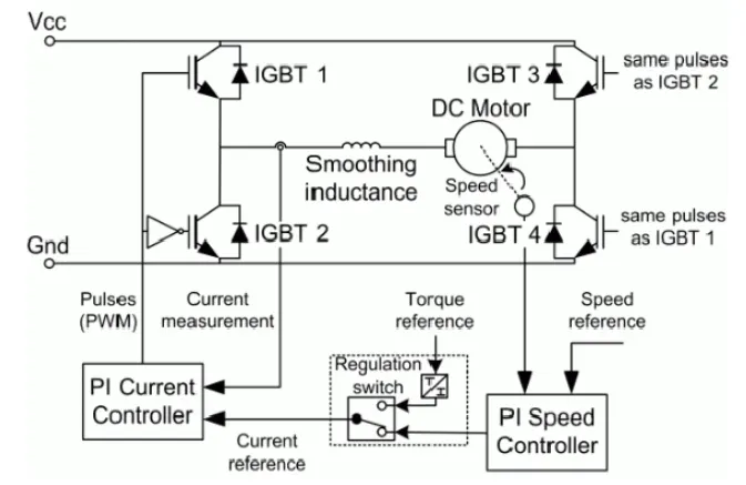
Working:
4 IGBT switches are used
Pulses are given from PI current controller that controles the pulses by comparing armature current and current reference
Current ref can be generated by using regulation switch in that torque ref and PI speed controller pulses that internally compared by speed of motor and ref speed .
Here speed is controlled by current controller
Forward motoring mode ,regenerative breaking mode : Q1,Q4 are on and Q2 Q3 are off
Reverse motoring ,regenerative breaking mode Q2 Q3 are on and Q1 Q4 are in off
Comparison
Here speed is controlled by Current controlling whereas in H bridge by controlling duty cycle.
Here regenerative breaking is der
Here smoothing inductance is der to smooth the current increase and decrease pattern where as in Hbridge its not present.
Here the operation is dicrete and der it is continuou.
2. Develop a 2-quadrant chopper using simulink & explain the working of the same with the relevant results. (Refer to article - Multiquadrant operation of motor )
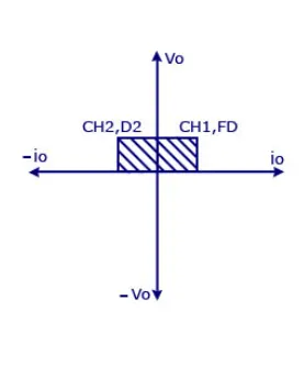
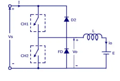
Vs =dc voltage source
CH1=Switch 1
CH2 =Switch 2
D2,FFD=Free wheeling diodes
E = Back emf
L=Inductor load
Mode of operation
When CH1 is on current flows from positve to load to negative terminal through L and E
CH1 is off the FD conducts ,voltage and current is positive
When CH2 is on current flow from E completes the circuit in negative direction.
when ch2 is off current passes through D2 towards the source in this stage regenerative breaking occurs.
2 Quadrant chopper model 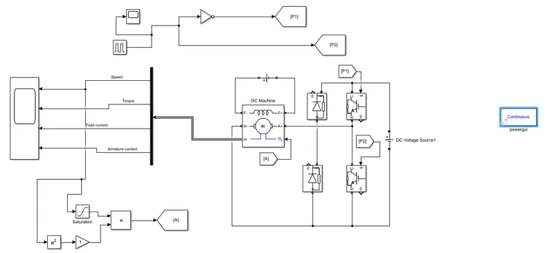
Below are the waveform generated
Pulse generator output
3. Explain in a brief about operation of BLDC motor.
Brush less dc motor having high efficiency and is also known as Synchronous motor.
Operation
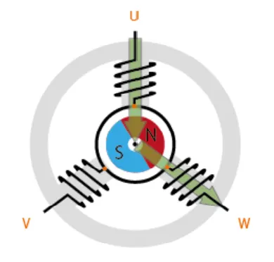
Let the 3 windings be U V W
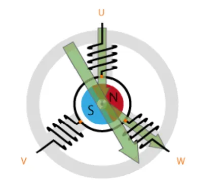
The current moves from U to W due to magnetization the coil attracts the rotor which makes the movement as shown by large arrow.
By switching the flux rotation is maintained so that the permanent magnet is chasing the rotating magnetic field.
The movement are acheived by cont. change in current direction over the two poles of the stator.
this two pole current method will start vibration in the motor therefore current flow should be in 3 poles so as to attain smooth rotation.
Control of BLDC motor
By using the inverter circuit to adjust the voltage into each coil we can control the magnitude of the current
One method is to use PWM technique i.e pulse width modulation technique ,We change the voltage by lengthening or reducing the pulse on time.
i.e Duty cyle ,Increasing the duty cycle has the same effect of increasing the voltage and vice versa.
120 degree conducting control only require 2 phase voltage control.
Sinusoidal control uses 3 phase voltage control and is considerably more complicated.