Week - 4
Part 1:
- Implement control logic of a “washing machine” using Stateflow as per given sequence:
- If the power supply is available, the system gets activated
- If the Water supply is not available, stop the process & indicate through LED
- Soaking time should be 200s followed by Washing time of 100s.
- Then rinsing happens for next 20s & dryer runs for 50s
After all the processes have completed turn on the finished LED
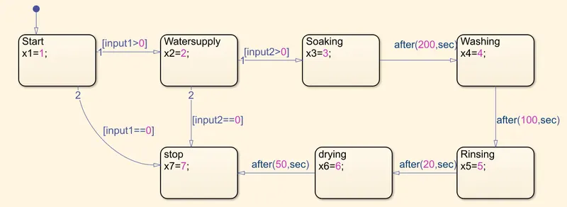
We have used chart for modelling washing machine function with x1 -x7 as outputs and input 1 as power input and input 2 as water inlet input.
as soon as the input condition satisfy state transition occurs i.e from one state to another state,this is the basic principle of state flow.
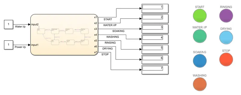
Red Led indicates finished state which is shown by stop indication. If the input power is 0 it will indicate red signal as well as if the water inlet is 0 then also it shows a red indication and if the process is over then also it indicates red signal.
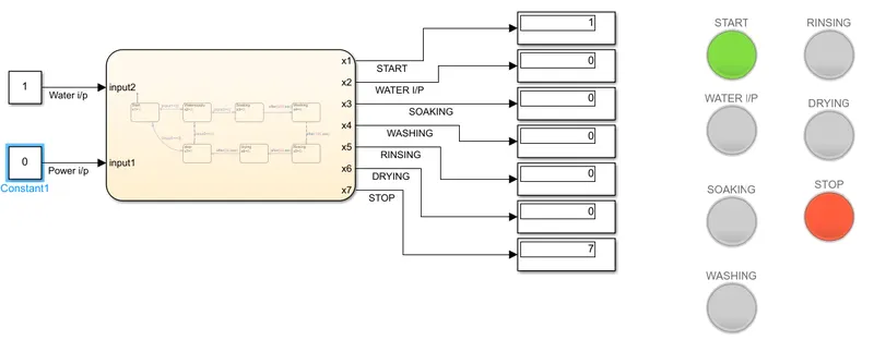 when Power is zero
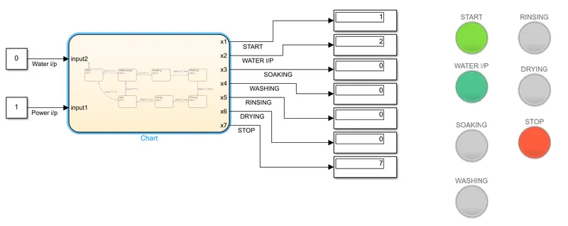 when water inlet is 0
Part 2:
2. Make a Simulink chart for the “Gear shift” logic as per below conditions:
Speed Range(kmph) Gear
0 to 15 1
16 to 25 2
26 to 40 3
41 to 60 4
Above 61 5
Give speed input while the simulation is running & display the gear number.
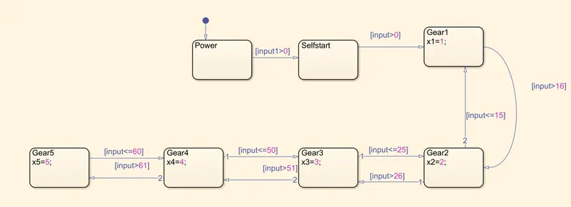
1)Input 1 is given to start the vehicle.
2)After then gear cycle starts with the inputs provided to input=speed,breaking point is 16 upto61.
3) up arrow indicates when speed decreases from 61 to zero,gear also decreases.
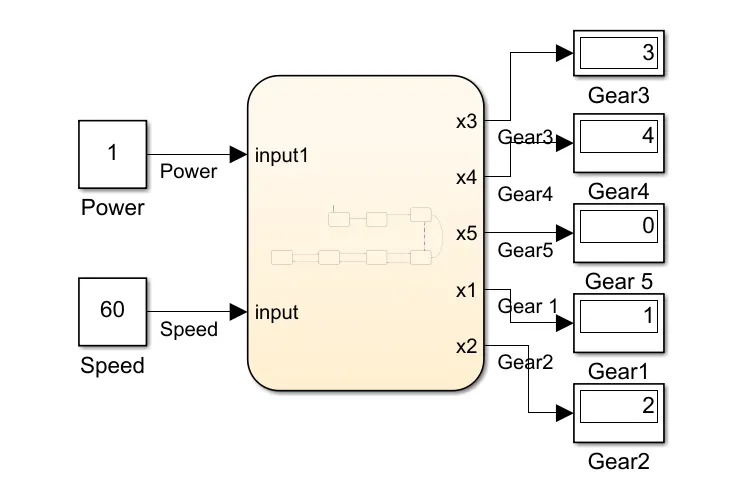 4th gear when speed is 60
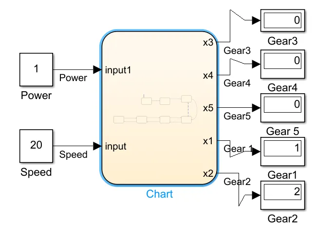 2nd gear when speed is 20
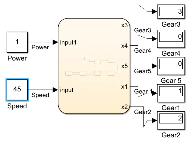 3rd gear when speed is 45