Week-7 Challenge: DC Motor Control
Q_1]
A._____ Explain a MATLAB demo model named ‘Speed control of a DC motor using BJT H-bridge’.
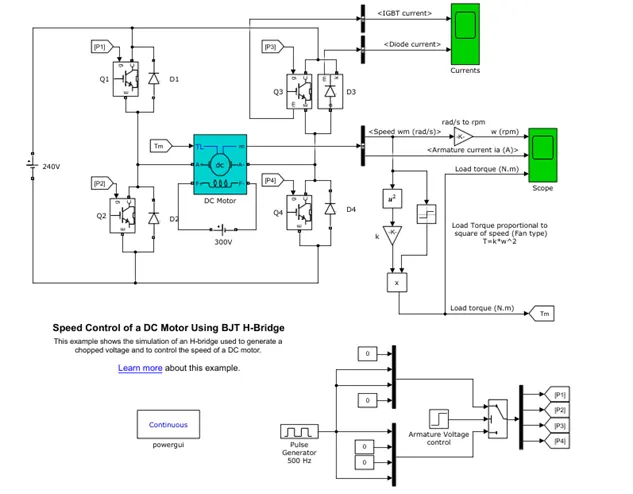
The above image is the MATLAB model of the DC motor with speed control with the help of H- Bridge.
For the formation of the H-Bridge there are four switches Q1, Q2, Q3 and Q4 are used. At a time two switch will conduct to give the specific direction of rotation.
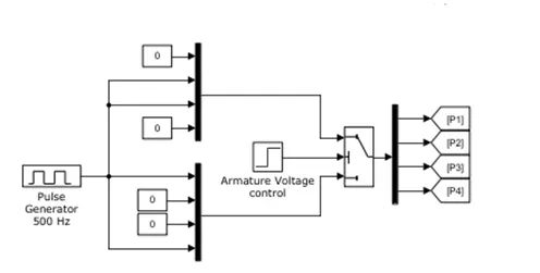
The above arrangement is for the armature voltage control. Which control the direction of the rotation by providing the appropriate device switching. Speed can be changed with the help of Duty cycle provided on the devices.
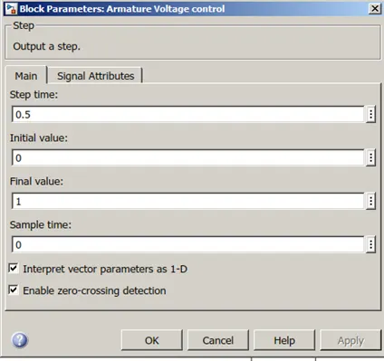
As seen in the dialog box named Armature control. IT is nothing but a step signal which helps motor to change the direction of the motor, as it is connected to multiport switch.
As the step time is 0.5, the signal state will change from 0 to 1 at 0.5 time. As per the condition till 0.5 second the switch P1 and P4 will conduct. Then after switch P2 and P3 will conduct hence the direction of the rotation will also change.
The load type for this simulation is fan load, where the torque is proportional to square of the speed.
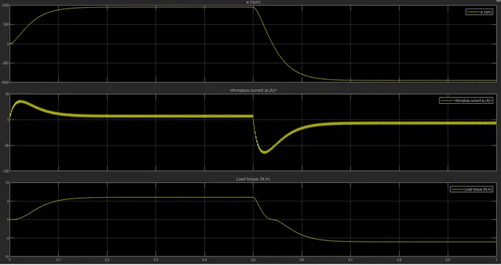
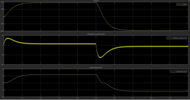
As seen in the result the motor runs in the positive direction till 0.5 sec and then it changes the direction of the rotation.
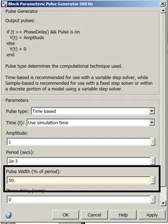
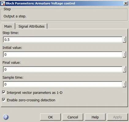
By changing the dury ratio ti 50%( reduced from 75%) and choosing the direction of the rotation in only one direction.
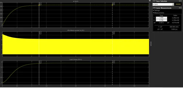
As seen from the above result it can be seen that as the duty ratio changes the speed of the motor also changes.
B.______
The equation for terminal voltage of the DC motor can be given by
`V = I_a R_a + E_b`
Hence Armature current is given by
`I_a = (V – E_b)/(R_a)`
At the stating there is no magnetic effect on the rotor of the dc motor and there is no back emf
`E_b = 0`;
Henec the Armature current is given by
`I_a = V/R_a`
So at the starting of the dc motor there is no current limiting back emf. Hence at the starting the armature current is higher. As the speed increases the emf build up and current start to reduce.
Suppose V = 230;
`R_a`= 0.3;
At the starting `I_a`= `230/0.3` =766.6
Suppose at the steady state the back emf `E_b`= 200;
Hence at the steady state `I_a` = `(230-200)/0.3` =100
The current at the starting is 7.6 times more than steady state.
C._____Refer to the help section of ‘The Four-Quadrant Chopper DC Drive (DC7) block’. Compare it with the H-bridge model.
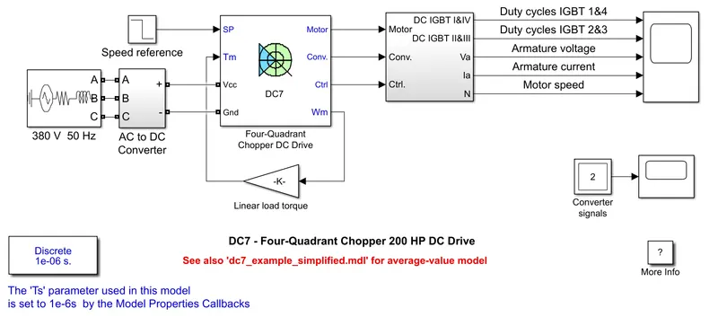
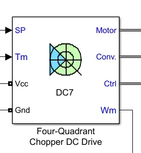
In that model the AC supply is given. That AC supply is rectified to obtain DC supply.
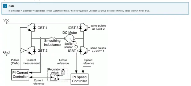
That DC supply is used for the four quadrant chopper,which can operate in all four quadrant.
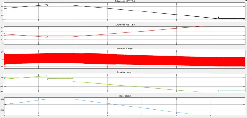
As seen in the figure the duty cycle of the all 4 switch is variable at the same rime, hence the the two switches from the each lag conduct simultaneously. It will help to produce the desired output.
The control of the four quadrant is takes place from the reference signal which is generated from the actual speed torque and speed and referece speed and torque.
The main difference between the H bridge model from previous section that
- H bridge model is open loop model and Four Quadrant DC7 is close loop model of H bridge
it is clear that the H bridge model has the control of open loop irrespective of the speed and Torque.
in given D7 model the switching of the device is based on the reference given to block.
- The regenerative breaking is not possible in the H bridge. While the four quadrant chopper provide the regenerative breaking.
- The h bridge is mainly used for the speed control of the DC motor in the both the direction.
- In the given model the four quadrant chopper operates with the closed loop control, which sense the output of the motor and motor current. And according to the switching pulses are given to the inverter.
- In both model the same fan load is connected.T = k w^2
Q_2: Develop a 2-quadrant chopper using simulink & explain the working of the same with the relevant results
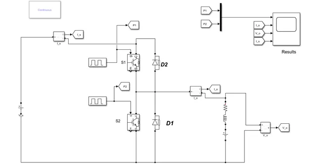
Mode 1: S1 ON
When switch S1 is ON the inductor starts charging exponentially and that current is the drawing from the supply. At that interval I_s = I_o
Mode 2: S1 OFF D1 ON
When S1 Drop conducting the D1 diode start conducting which is called Freewheeling action. After that if no switch operated the inductor current die out to zero.
In freewheeling action, the source current is zero.
Mode 3: S2 ON
When S2 conduct the battery connected series with the inductor starts charging inductor in the reverse direction.
In that case no current is drawing through the supply. Hence Source current is zero.
Mode 4: S2 OFF D2 ON
The stored energy in the inductor now flow through D2 to back to the source.
At that time the source current is negative as the current floes in the reverse direction.
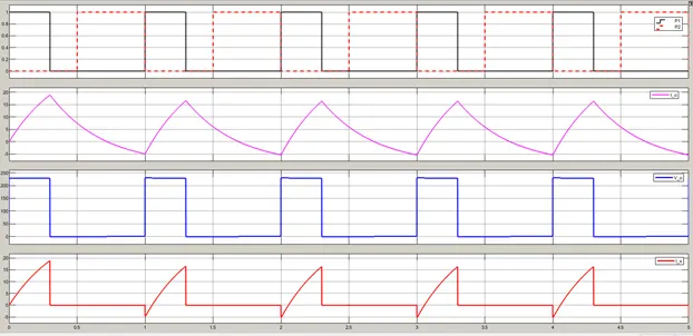
In the above plot first is pulse 1 and pilse 2 for switch S1 and switch S2.
second is output current, third is output voltage. and last one is the source current.
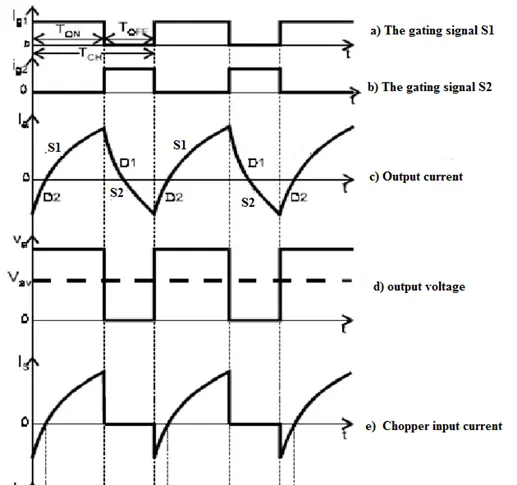
Above waveform are theoretical which are matching to the simulation results.
Q_3:Working if the BLDC motor
The Basic understanding of the working of BLDC motor is that it works on the principle of “Man sitting on the donkey driving by carrot on the stick” :-)
In our case
Donkey – Magnets on the rotor of BLDC ( Motor )
Man – we and the main controller with inverter
Carrot - the magnetic field produced by the inverter
Stick - Hall effect sensors( keep pusing rotor with the help of inverter and controller(Inv.))
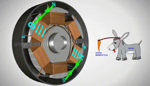
(In this image Stator is in the inside and rotor is outside i.e., Cooling fan used in Computer and imagine man is driving donkey with the help of stick with carrot)
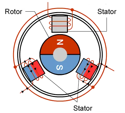
As seen in the above figure the magnet try to reach to the opposite polarity eletro magnet on the rotor the electro magnet disconnects from the supply or change its polarity.
We can give the command according to our need and controller will going to change the command signal for the inverter. Then inverter is going to produce the required magnetic field and polarity to rotate the rotor in controlled manner.
BLDC motor has the construction similar to the induction motor for the stator side. The only difference is that BLDC has permanent magnet of its rotor.
For the controlling BLDC motor the Inverter is the essential thing, without that BLDC motor is useless.
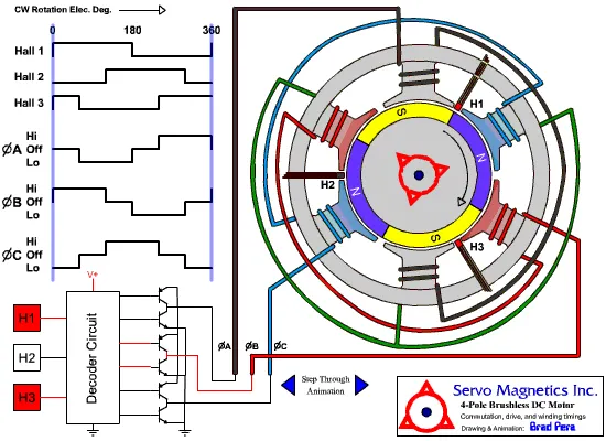
steps:
- Hall effect sensors sens the position of the rotor.
- The signal from hall effet sensor will go to the controller of inverter.
- The controller will comare the desired and the actual rotor position and hence speed.
- Controller will produce control signal and provide to the inverter to produce commanded output.