Week - 4
Aim: 1. To implement the logic for Washing Machine using state flow
2. To implemet the gear shift logic using state flow
1. To impleent the logic for Washing Machine using state flow
##Blocks used for the simulation##
•Chart
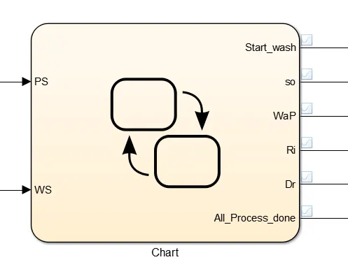
This block is used to implement any logic based on condition.Whenever the condition is true the block action start executing. This block is used to implement state flow logic implementation
•Lamp

This block is used to indicate colour based on the condition given in the block.
For example we have green on state 1 and read on state 0, whenever the state is true according to to the lamp will be glow.
In the simulation it is used for the indication of the completion of the process. Whenever the process compete the lamp indicate the green light.
•Constant
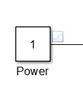 Constant block is used to to give any constant value to any block i.e, Chart
In the simulation this block is used to provide the power supply and water supply.
•Display
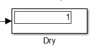
This block is used to indicate the value of a block connected to it on every sample time. Here it is used for indicating the process completion.
- State

This state block is used to implement the condition acrion statement. Whenever the condition for that block is true the block action start to execute.
- Switch
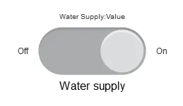
In simulation this switch is used to switch on the power supply and to turn on the water supply.
It switch between any two state.
##Results For Washing Machine state flow##
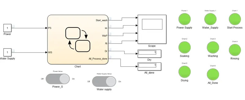
This is the model Build for the Washing machine. Here the lamps are for the process indication.
Red light means the process is not completed or ongoing.
Green light means the process is completed.
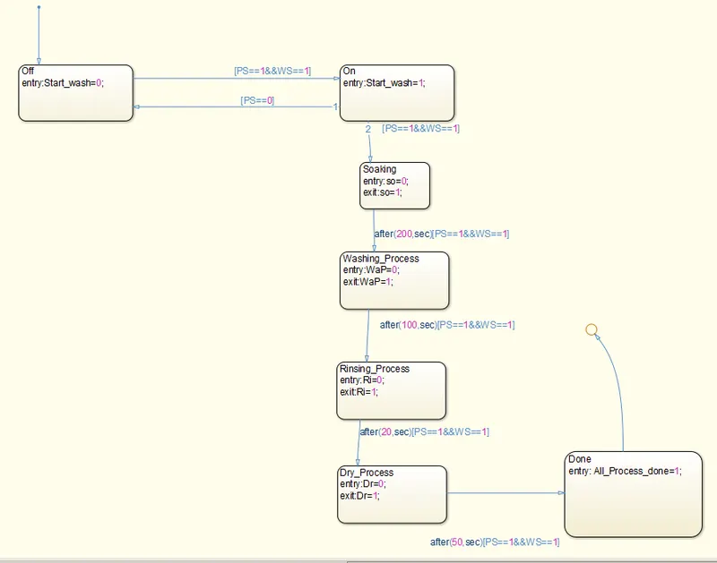
This is the state flow diagram that indicate the control action along with their condition to execute.
First the checking for the water supply and te power supply is there.
Then The process is as follows
200 sec -----> Soking _Then Lamp : green
After 100 sec----->Washing_Then Lamp : green
After20 sec----->Rinsing_Then Lamp : green
After 50 sec----->Drying_Then Lamp : green
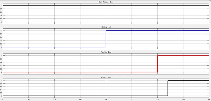
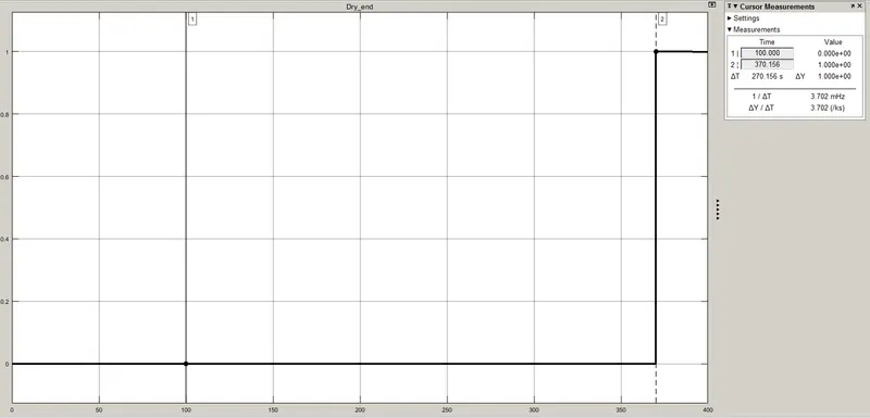
The above are all process soking,washing,rinsing and drying.
The Pulse shows that te process is done ,at that step time.
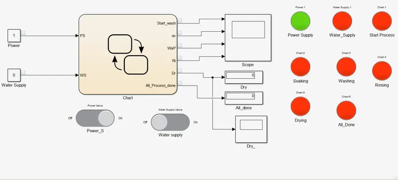
Now The above image is representation when the water supply is off. Only the power supply is on that's why the lamp for it is green. And for rest of that the Lamps are red means the process is stopped.
2.To implemet the gear shift logic using state flow.
##Blocks used for the simulation##
- Chart
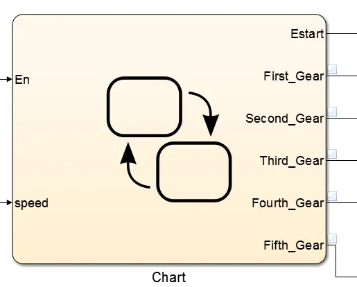
Chart is used to implement the state flow logic implementation as mention before. Here It is used for the implemetation for the Gear shift logic implementation.
- From and goto block
Go to block will transmit the signal and the from block will connect that transmitted signal.
It is used to improve the appeareance of the simulation.
- Lamp

Lamp is used to indicate the state as per the settings given for the given respective setting
- Slider Gain
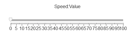
Slider gain block is used to change the value of any given block connected to it.
It is used to change the values during the simulation.
Here that block is used to change the speed with the running simulation.
- Toggle Switch
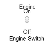
Toggle switch is used to change the state of the any block connected to it.
In the simulation it is used for the Start of the Engine. It act as the on off sitch of the engine.
##Results##
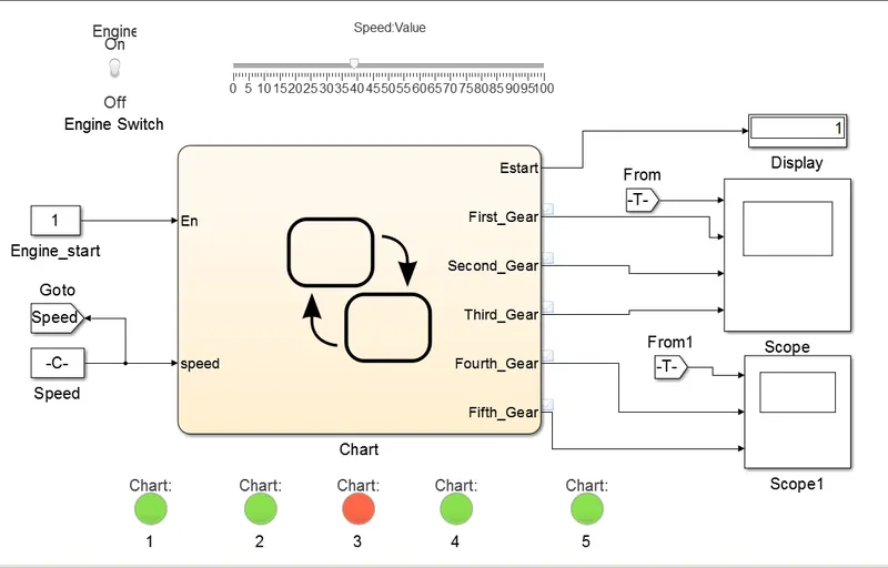
This is the model prepared in the matlab. The slider gain is is used as a speed adjuter.
The speed condition are as per the given in question
In above simulation the speed set is around 40, so as per the condition the third gear is set indicated by the red light.
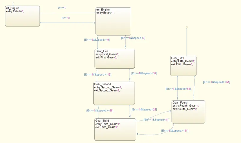
For speed 0 to 15 Gear 1
For speed 16 to 25 Gear 2
For speed 26 to 40 Gear 3
For speed 41 to 60 Gear 4
And for Speed Above 61 Gear 5
To change the speed during simulation the simulation time can be changed from any number to inf for infinite run time.
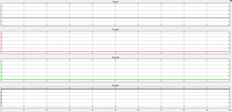
The above results are for the speed of 40. It trigger the 3rd gear as per the condition. Hence the simulation for the gear shift is successfully implemented in the matlab software.