Project
Aim: To carry out the system-level simulation of all-terrain vehicle.
Objective: To prepare the technical report and to comment on the results for given model.
Blocks used to perform the simulation
Signal Builder
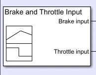
Signal Builder is usually used for to build any signal at given time according to requirement. In the simulation the Signal Builder is used for the generating the throttle and the brake for the input of the engine.
Generic Engine Block
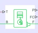
This is the generic engine block used to implement the engine behavior according to the input given to it, which are throttle and brake input as shown in the image. B represent the engine block which takes the rotational reference. P provide the instantaneous power produced from the engine, FC represent the fuel consumption, F is the crank shaft which is connected to the CVT system.
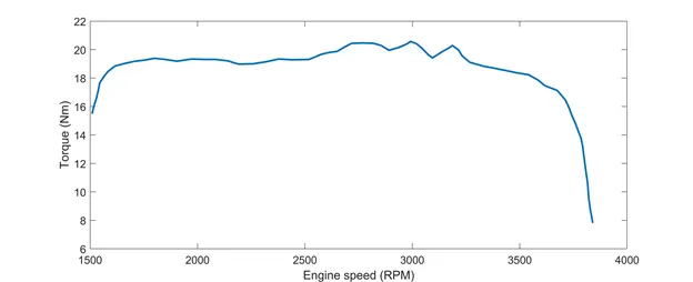
The above image is the engine behavior of the engine. This graph helps to implement the generic engine block. The data points from the graph are extracted using GRAB application and that data points are used for the implementation of the engine block.
RPM sensor
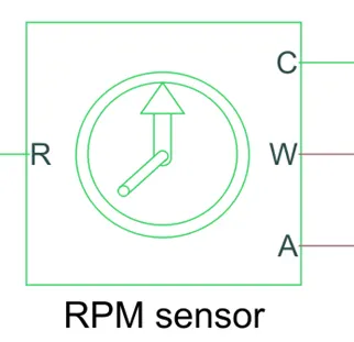
RPM sensor is used to sense the RPM of connected lock to it. In the simulation it is connected to the engine block which measures the primary velocity and the other connected to the secondary of the variable gear ratio block, which will give the secondary velocity of the CVT.
Variable Ratio Gear
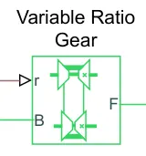
As name suggest it has a variable gear ratio. It provides the gear ratio according to the requirement of the user. In the simulation the variable gear ratio take the value from the signal builder and lookup table depending upon the speed.
Simple Gear
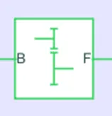
As name suggest it is the simple gear which helps to convert the speed higher or lower according the fixed ratio given into the block. It is different from the variable ratio gear which operate for the variable gear ratio during the operation.
Vehicle Body
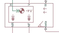
Represents a two-axle vehicle body in longitudinal motion. It has various inputs like W for the wind coming from the front of the vehicle, Beta is the inclination angle at which the vehicle travel on the road NR and NF are Rear and front wheel normal forces. V in vertical motion and H is for the Horizontal motion.
Tire
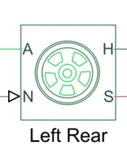
This is the model block of the tire which convert the rotational motion given to it to linear translation motion.
Double Shoe Brake
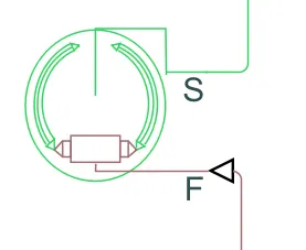
It is the mechanical part of the vehicle system. Double shoe brake is used for providing the brake to the system and stop the vehicle.
Lookup Tables
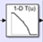
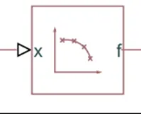
Lookup tables are used to operate on specific point for the given point to it. Generally, it has a data in the table form with reference value and the main output value. So when the reference value is get to the input of the lookup table it seeks for the corresponding value of the reference point and give that value in the output.
custom gauge
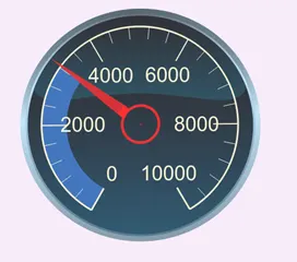
Custom Gauge is used to indicate any value connected to it. In the simulation it is used for the velocity and RPM of the vehicle.
Knob
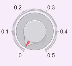
Knob is used to change value during the simulation. This block is similar to the slider gain. The working of the both of the block is same, only the representation is different.
Working of The Model:
#First Model and second Model (Independent CVT ratio)
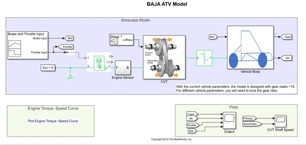
This is the ATV model which is used for the continuous variable transmission system.
At first the throttle input is generated through the Signal builder, which is used for the provide the input speed to the generic engine. After that the engine sensor is used where the speed or the velocity is measured from the generic engine. For the sensing the velocity, engine sensor uses the RPM sensor is used.
After that the Speed input is given to continuous variable transmission system. CVT takes the input as a speed and the CVT Ratio. These both the input are used for the variable gear system Which is pulley- Belt arrangement.
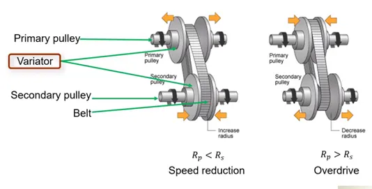
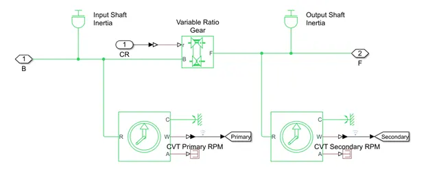
This pulley- Belt arrangement is varying according to the CVT gear ratio given to the variable system. According to the gear ratio the speed is increased or decreased by the shifting the pulley to increase the or decrease the diameter of the pulley.
Then the simple gear ratio is used for the changing the speed according to the gear ratio provided.
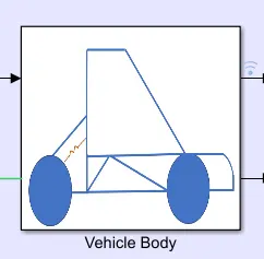
Now, Finally the speed and brake inputs are given to the vehicle body in which the tire, double brake shoe and vehicle upper body are placed.
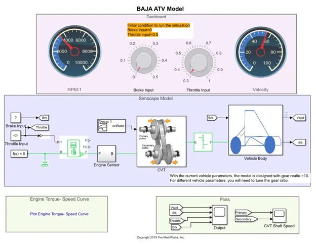
This is the second model, where the difference is only dash board system. In that the throttle and brake input are can be changed during the run time of the simulation. It can be observable that increasing the throttle input the speed is increases.
Note here that in the first and second Model the CVT ratio is chosen Randomly and it can be anything and not dependent on any other parameter from the model, Chosen by the user.
##Results for 1st and 2nd model##
#1st Model
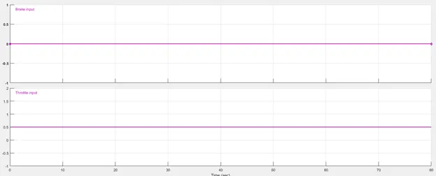
Here the throttle is set to 0.5 and the brake input is set to 0 as brakes are not applied.
This inputs are given to the Generic engine, from that engine speed is sensed.
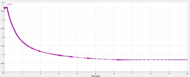
The above image is for the CVT ratio input to the CVT system. CVT system takes CVT ratio and the speed. According to that it vary the speed.
The Velocity before CVT and after CVT shown below.
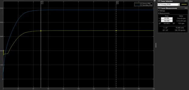
The primary speed is 3400 rpm and secondary speed is 4860 rpm.
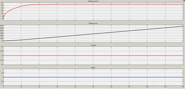
The above Scope output shows the throttle, brake inputs and Velocity and distance after the vehicle body (output from full system).
#2nd Model
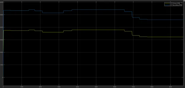
This is the CVT velocity. As this output is for the variable throttle input the primary and secondary velocity are varying.
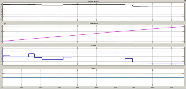
Similarly, these are also for the variable throttle input and hence it has variable performance. Only the Distance is linear as it shifts from one place from the other with variable speed, but it is not still.
##3rd Model Results##
The working of this model is similar to 1st model so here only results are explained.
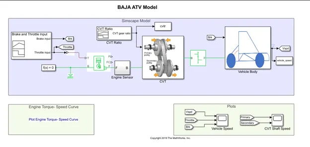
This model is similar to the 1st model where the CVT ratio is independent.
Exactly that thing is done here, The CVT ratio is changed.
In addition, it transfers the data of CVT ratio and the velocity to the workspace of MATLAB window, where it can be used in the script.
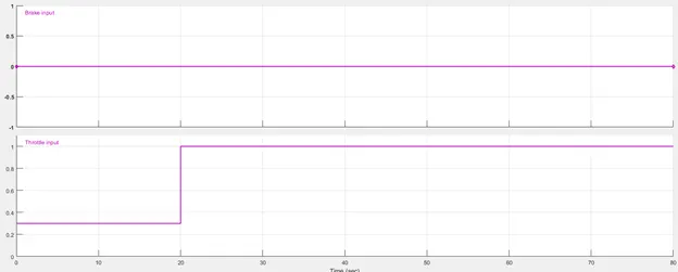
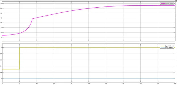
In above image shown that the throttle input is changed from 0.3 to 1 at 20 second. It means that at that time the speed will increase at fast rate before 20 sec.
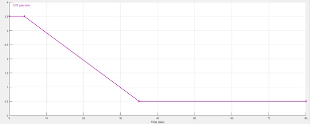
Here the CVT ratio is changing, it is observable that the CVT ratio at 30 second is unity. That means the speed at the primary and secondary CVT will same. After that the CVT decreases that means the speed of secondary CVT will less than the primary. After that it continue will constant value less than 1, that means the speed of secondary will be always less the primary.
Let’s see the conclusions from the above observation.
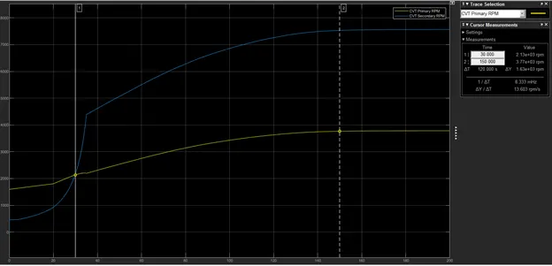
Exactly getting what we are expecting!
After 20 sec it raises more rapidly as the throttle value is increased.
It crosses at 30 sec and after that primary velocity is more than secondary velocity.
##4th and 5th Model Results##
#4th Model#
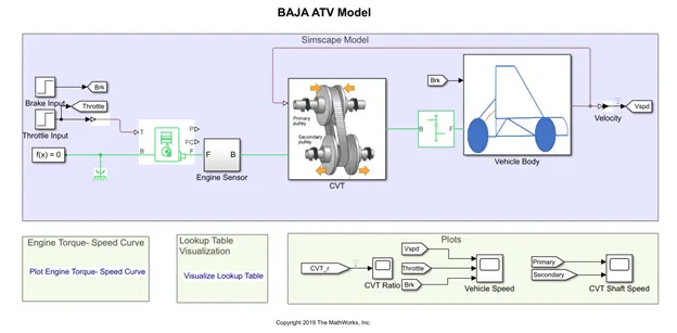
This is the model which is similar to previous one except the CVT ratio. It is generated by the lookup table which is depends upon the vehicle speed.
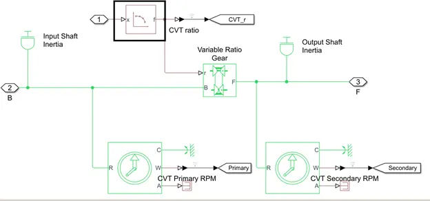
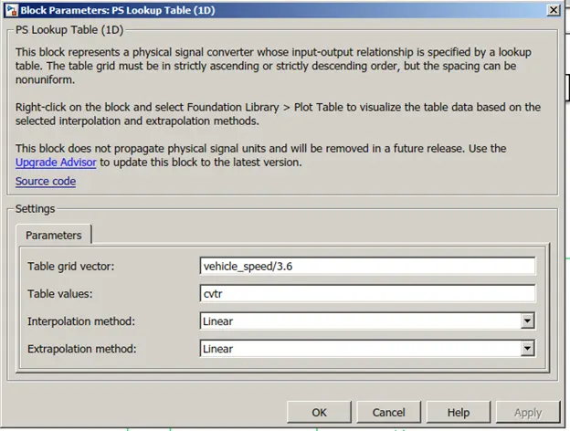
As seen in the above image the lookup table is place which selects the CVT ratio according to the Vehicle speed. It uses the cvtr from the lookup table from the Lookuptable_data.mat file
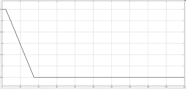
Above figure represent the CVT ratio with respect to time. It changes according to the speed.
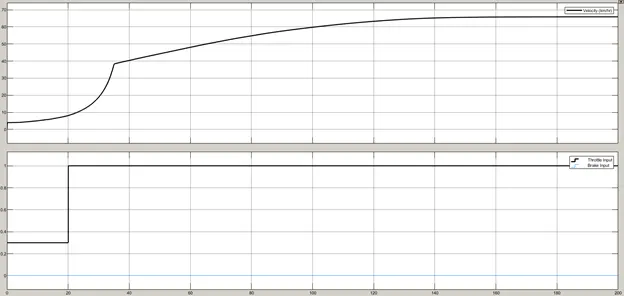
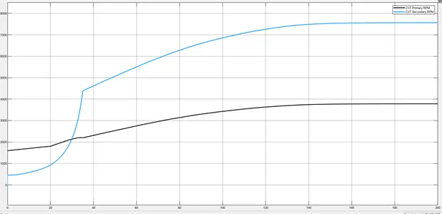
Rest of results are same as previous as the operating point same which are at 30 sec the throttle value changes from 0.3 to 1 and at the 20 sec the throttle value crosses the unity value and sets to the below unity value.
#5th Model#
This model is same as previous, with addition of the dash board.
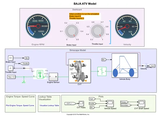
This is the model in for the CVT for the lookup table arrangement for the CVT gear ratio.
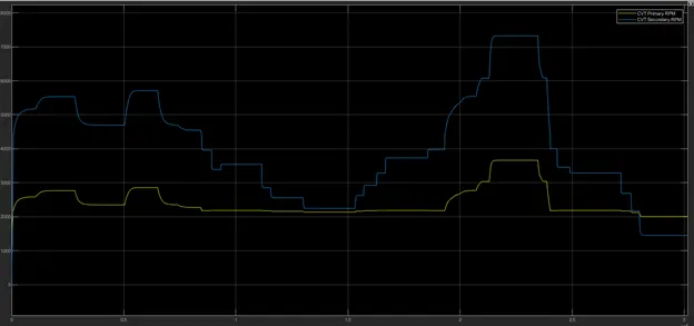
The above represent CVT primary and CVT secondary according to the throttle value.
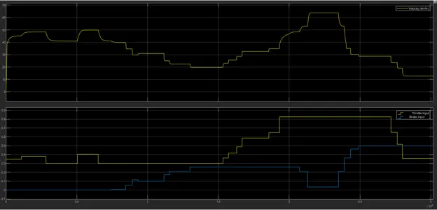
The above scope output is representing the final output velocity along with the throttle value and brake input.
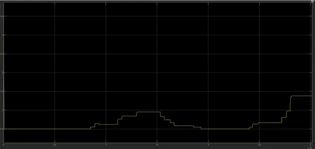
This is the CVT ratio changing according to the speed of the vehicle.
##6th model Results#
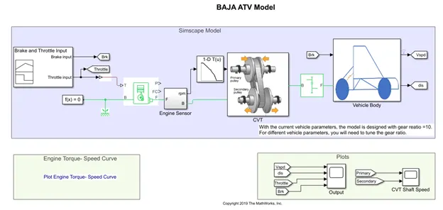
In previous model the CVT ratio depend upon the final value of velocity of vehicle, but here the CVT ratio depends upon the Primary velocity from the engine. It seeks the value of CVT ratio according to the RPM from the engine.
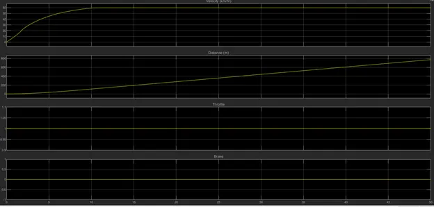
This is the Scope output for the Look up table method Simulation model for the CVT. The throttle value is at 1 value and the brake at the 0 value.
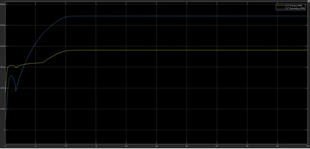
This is the primary and secondary velocity from the CVT system. The gear ratio of the variable gear is depending upon the RPM from the Engine. The values for the lookup table are taken from the Lt_cvtratio_rpm.mat file.
Conclusion:
In the given model the CVT system is implemented with variable ratio gear. In the various model the strategy to change the gear ratio is taken different. In some initial model, this ratio is provided from the signal builder block and later on the lookup table approach is used. The Dash board system is very helpful to visualize the response of the vehicle for the CVT.