Week-7 Challenge: DC Motor Control
1. Question (1) :-
(A) Explain a MATLAB demo model named ‘Speed control of a DC motor using BJT H-bridge’.
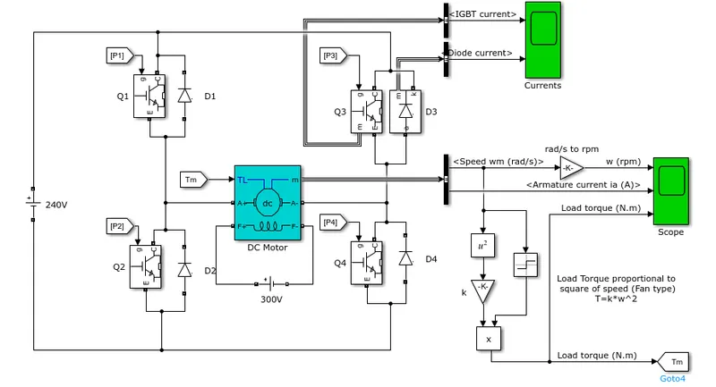
- Above is the demo model of speed control of DC motor using BJT H bridge ,it consist of following blocks:-
- DC motor
- IGBT along diode
- Voltage source
- Square ,gain
- goto ,from
- Signum ,scope,switch, pulse generator and constant .
Details of each block are as follows :-
1. DC motor:-
- Specification of motor is 5HP, 240V,1750 RPM and Field voltage 300V. The value of R,L is set as by default.
- In general DC motor is model as R-L-E load .
- R is the resistance of armature conductor,L is the indutance effect and E is the back emf generated due to Faraday's law of EMI.
- In the block of dc motor there is F+ and F- terminal where field winding connection to be made and it is supplied by 300volt.
- There is armature connection terminal A+ and A- where H bridge circuit is connected.And to apply any load TL port is also available.
2. IGBT with diode:-
- Actually Speed control has to be done with help of BJT but due same switching characteristics as IGBT it is dine through IGBT.
- Four IGBT is used for speed control of DC motor ,the arrangement of IGBT looks like H bridge.
- A anti parallel diode is connectred across each IGBT .This diode is called as free wheeling diode,which can protects the switch from getting damage due to sudden trasition .
- Each IGBT is controlled by some controlled pulses that is when to ON and OFF.
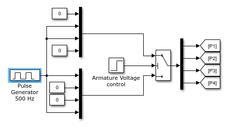
- Pulse generator specification :-
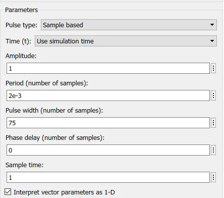
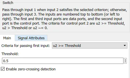
- Switch is used to decide when and which IGBT get triggerd.
- Thereshold is set to 0.5.
3. Fan load :-
- Torque -speed equation for fan load is :-
- T=k*w^2
- Which is model in above diagram.
- Working:-
- There are four IGBT switches present name as 1,2,3,4 along with its own body diodes.
- Any two will on at a time .
- When switch 1 and 4 on a positive voltage of 240V is applied to the armature terminal of DC motor and motor starts rotating in forward direction.
- When switch 1 and 4 gets off as there is sudden change in current and DC motor contains inductance it won't allow to do so ,so it opposes with help of back emf by producing a sharp spike this is dangerous for switch it may burn.so,to prevent from this a diode gets turn on 2 and 3 to free wheel that current.
- When switch 2 and 3 are on a negative voltage get applied across DC motor and motor direction get reversed.
- Graphs:-
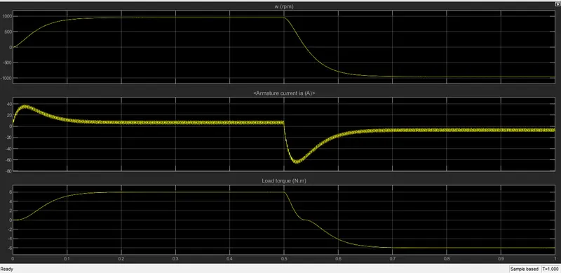
- If we see speed graph , slowly the motor catches the speed and contant to some value as per the load demanded.
- From 0 to 0.5 second switch 1 and 4 is on so motor rotate in forward dirction and speed seems to be positive.
- After the threshold reached that is 0.5 sec , switch 2 and 3 get on and motor direction reverses and it is shown with negative speed.
- Focusing on load torque graph , as torque is proportional to speed it follows the same pattern as speed but little parabollically,by considering the threshold point.
- In armature graph is discussed in question b.
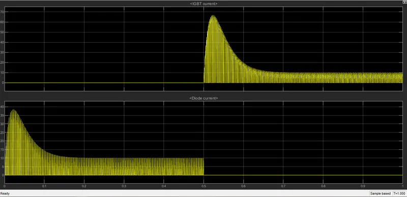
- Above is the IGBT and diode graph.
- As discussed when IGBT are conducting diode won't coduct and vice -a-versa.
- Current flowing through IGBT and switch is same as armature current . so nature is same that is intially shoot up and falls to constant value.
B. Comment on the armature current shoot-up from the scope results.
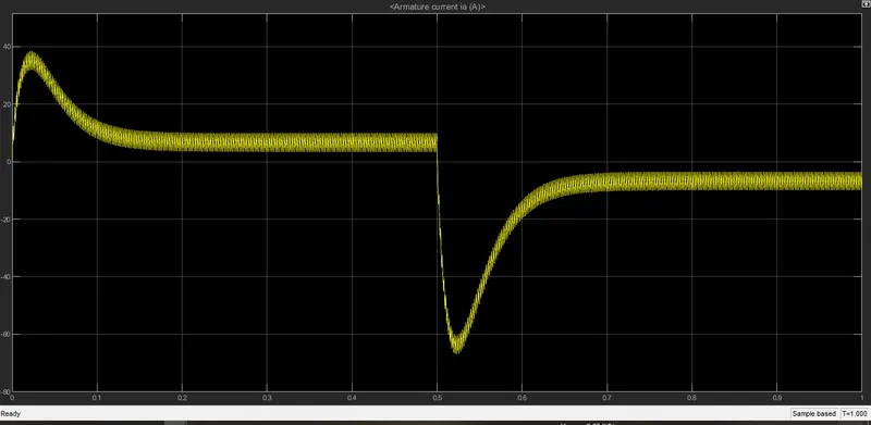
- Above is the graph shown the armature current of DC motor with respect to time.
- As, the switch 1 and 4 on the positive voltage applied across armature and current starts to flow.
- As dc motor is modelled as RLE the inductor starts charging as shown by increasing in current.
- At start back emf of motor is zero therefore current drawn by motor is very very high and as speed builts up the back emf is also developed in motor(back emf is porportional to speed). I=V/ra
- I=(V-E)/ra
- Due to which it oppose the applied voltage and current starts reducing and settles to particular value as shown in graph.
- At 0.5 sec threshold is reached switch 1 and 4 are off and switch 2 and 3 are switched on ,motor negative voltage is applied across dc motor leds to negative flow of current,as shown.
C. Refer to the help section of ‘The Four-Quadrant Chopper DC Drive (DC7) block’. Compare it with the H-bridge model.
Following are some of the point's to be consider for comparision between the two :-
| H-Bridge model | DC-7 model | |
| Method of generation of Triggering signal's of IGBT | Generation is done through conventional and simple approach,with help of pulse generator. | Generation is done with help of control system ,comparator and sawtooth generator it is advance approach. |
| Armature current | In this armature current waveform is suddenly shoot up as switches are closed abd then decreases. | In this armature waveform is slowly increasing to desierd value and decreases step wise. |
| Waveform of triggering signal of IGBT | In this Waveform is in rectangular shape ,suddenly increased then constant for sometime and suddenly decreased. | In this waveform is increased then linearly increased then constant for some time and decreased linearly. |
| Solver configuration used |
It uses variable step solver. |
It uses fixed step solver |
| Load torque | Here load torque is proportional to speed square. | Here loadtorque is linearly proportional. |
| Construction | It contains dc motor ,hbridge,fan load,pulse generator. | It contaions rectifier ,DC-7 block(itself contains motor ,power converterand controller). |
2. Question(2) :-
Develop a 2-quadrant chopper using simulink & explain the working of the same with the relevant results.
Simulink model of 2-quadrant chopper are as follows :-
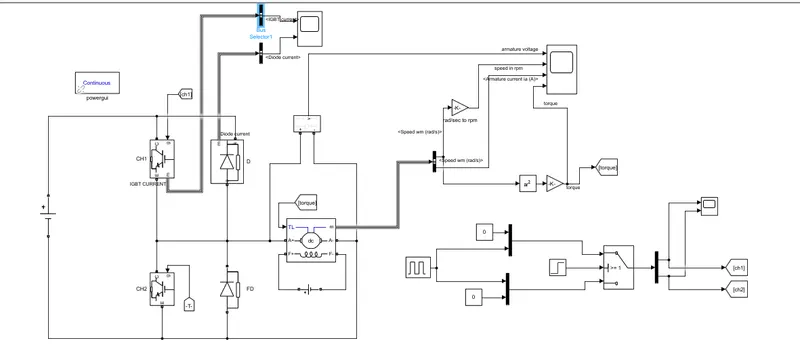
- Blocks used in above model are:-
- DC machine (5HP, 240V,1750 RPM and Field voltage 300V)
- IGBT ,diode
- pulse generator (time period=0.02sec,duty cycle=50%)
- constant,switch
- square,gain(k=30/pi and k1=6.062e-4)
- goto,from,scope,step,bus selector
- voltage source(240V and 300V),voltage measurement.
- power gui
Introduction of chopper :-
- Chopper is a circuit which can convert fixed dc supply to variable dc supply .
- It is widely used in electric vehicle application,wind and solar system,control of dc motor.
- Above is a two quadrant chopper .It consist of two chopper switch ch1 and ch2 with two diode .
- The two quadrant chopper is the combination of type A and type B chopper.
- When ch1 is on it behave as type A chopper and when ch2 is on it behave as type B chopper.
Working :-
- ch1 and ch2 are connected at same leg .Do not switched on both switches at same instant it will led to short circuiting of supply.
- When ch1 is on the supply get connected to armature terminal of DC motor and inductor stores energy and motor rotate in forward direction.
- when ch1 is off inductor discharges through free wheeling diode path is like L-E-FD-L.
- The direction of current is still positive ,therefore it lies in first quadrant (V=+ve and I=+ve).
- Now, when ch2 is on ,as dc motor is modelled as R-L-E load the E supply current through E-L-ch2-E.The direction of current is still positive.
- And, when ch2 is off then current flow through E-L-D-supply voltage-E.In this voltage across load is positive but current direction reverses.so, it lies in second quadrant.
- In this case load is delivering power to source it is called regenerative braking mode.
- If we summarize , In first quadrant it is forward motoring mode and in second quadrant it is regenrative braking mode.
Result's:-
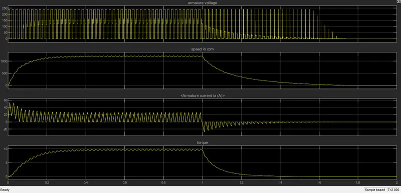
- Above is the plot of armature voltage,speed in rpm,armature current and torque.
- At 1 sec instant it is a threshold set means below 1 sec ch1 is on and ch2 is off and above 1 sec chi is off and ch2 is on.
- If we see armature plot in both the cases armature voltage is positive that is in motoring(below 1 sec) as well as braking mode(above 1 sec).
- In aramture current graph in motoring mode (below 1 sec) armature current is positive and in braking mode(above 1 sec) current is negative.
- In motoring mode speed increases and reaches to particular value and in braking mode it reduces and becomes zero.
- As torque load is proportional to speed square it will flow the speed curve but more parabolically.
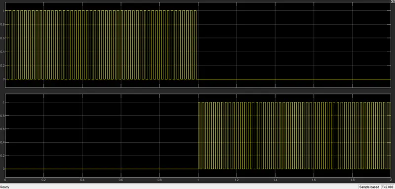
- Above is the graph of pulse generation to trigger the ch1 and ch2 .
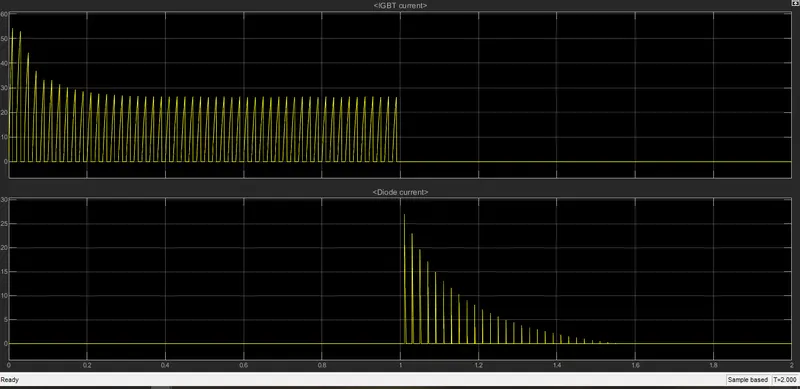
- Above is the graph of ch1 and diode current.
- It tells when ch1 conducts diode d does not conduct and when diode d conduct ch1 does not conduct.
3. Explain in a brief about operation of BLDC motor :-
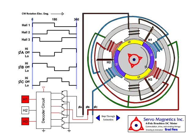
- BLDC(Brushless DC motor ) are also known as self synchronous AC motor , variable frequency synchronous motor, permanent magnet synchronous motor(PMSM) and electronically commutated motor(ECM).
- It can operate at speeds above 10,000 rpm in both loaded and unloaded conditions.
- Among the brushed dc motor and induction motor ,brushless dc motor has highest torque.
- In BLDC motor commutator and brushes are not use so sparking not happens and therefore no energy loss and life of motor increases and it can operates upto 10000 hours.
- Rotor of BLDC motors have low rotor inertia, allowing them to accelerate, decelerate, and reverse direction quickly.
- BLDC motor has good powerfactor and hysterisis and eddy current losses are also less .
- As machine size of BLDC increases magnetic losses are increase proportionally but this is not the case in induction machine.
- Without the inverter BLDC is useless .
Working :-
- Construction wise BLDC motor is different from Brushed DC motor.
- In BLDC motor permanent magnet is placed on rotor and coils are placed on stator.
- The movement of rotor is with the help of attraction and repulsion principle .
- On the stator three coils are placed and they are switched on and off according to rotor rotational position which is determine by position sensor with the help of Hall effect.
- Hall Effect sensor provides the portion of information needed to synchronize the motor excitation with rotor position in order to produce constant torque.
- It detects the change in magnetic field.
- The rotor magnets are used as triggers to the Hall Sensor.
- Three Hall Sensors placed 120° apart, are mounted on the stator frame.
- The Hall Sensor digital signals are used to sense the rotor
- For switching the stator supply current and electronic control is required that is inverter.
As BLDC has good peak point efficiency so it has its dominance in hybrid and plug in hybrid vehicle market.