Week-7 Challenge: DC Motor Control
1>>Ans: steps are as follows:
- The very first thing is to import the model of speed control of a DC motor using the BJT H Bridge.
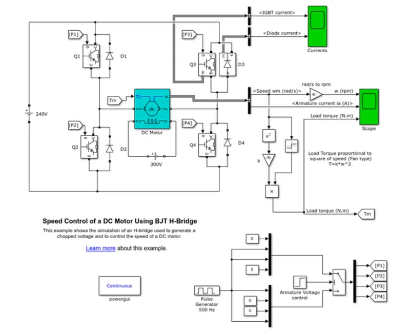
- Then the imported model of this BJT H Bridge mainly consists of the blocks DC motor, pulse generator, armature voltage control, IGBT transistor, diodes, the scope for plotted results, and other constant block and again blocks to calculate the torque output of the motor.
- so in this model, mainly describes or outputs the armature current, load torque, speed, and also currents of IGBT and Diode.
- The working of this model is that a motor rotates in the forward direction and then in the reverse direction.
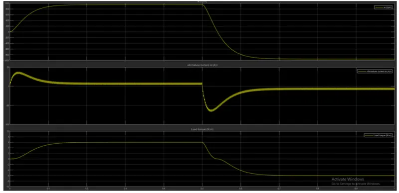
- So to decrease the peak change in the current we need to change the input signal generator's duty cycle to decrease the sudden shoot in the current.
- The model of the image is shown below.
The Armature current when the duty cycle percentage is set to 75% the graphs will be is as follows:
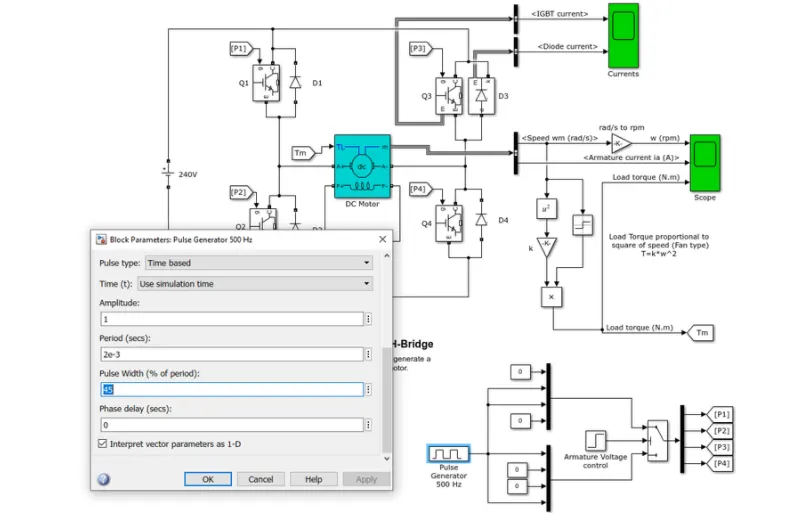
- So after changing the input signal generator to 45% of the total supply voltage the peak shoot in the armature current will be normalized.
- if we need to switch the motor operation like forwarding braking, reverse braking we need to change the supply to switches and diodes according to multi quadrant operation of a DC motor.
Output is as follows:
The change in the pulse signal is given in the below image:
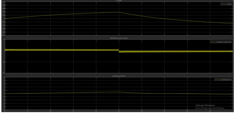
- The output of the armature current, speed, and torque results were given below:
- So from changing the duty cycle to about 45% we can see the reduction in the Armature current shoot peak.
- If the duty cycle keeps on increasing the output voltage coming from the bridge circuit to the motor will be getting equal to the input voltage motor.
- The motor duty cycle percentage can not be less than 30% as it decreases the ability of the motor to have rotation.
2>>Ans: CHOPPER DRIVE:
A chopper drive-based speed control is widely prefered as far as speed control is concerned choppers are mostly applied in electric cars, conversion of wind and solar energy and DC motor regulators. A chopper uses high speed to connect and disconnect from a source load. A fixed DC voltage is applied intermittently to the source load by continuously triggering the power switch ON/OFF. The period for which the power switch stays N and OFF are referred to as the choppers ON and OFF state times, respectively.
A dc to dc converter also known as dc chopper is a static device that is used to obtain a variable dc voltage from a constant dc voltage source. Choppers are widely used in trolley cars, battery-operated vehicles, traction motor control, control of large DC motor, etc. They are also used as DC voltage regulators. Choppers are of two types:
1>Step down choppers.
2>Step up choppers.
In step down choppers: the output voltage will be less than the input voltage, whereas in step-up choppers output voltage will be more than the input voltage.
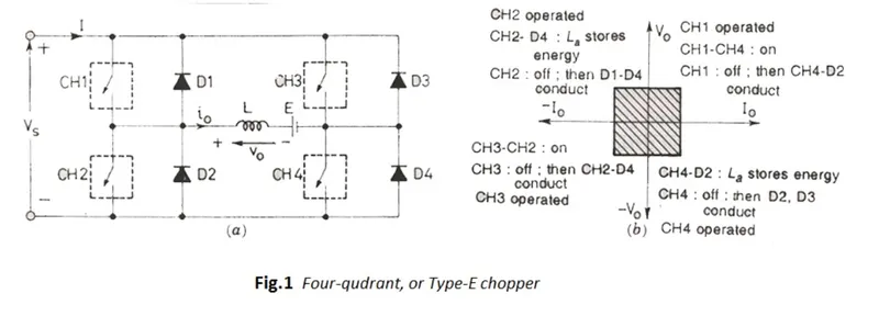
The four-quadrant chopper is a chopper that can operate in all four quadrants. The power can flow either from source to load or load to source in the chopper. In the first quadrant, a class E chopper acts as a step-down chopper whereas in the second quadrant it behaves as a step-up chopper. This type of chopper is also known as Class E or Type E chopper. This article describes the working principle and operation of a class E chopper with the help of a circuit diagram.
FIRST QUADRANT OPERATION :
for the first quadrant operation, CH4 is kept ON, CH3 is kept OFF and CH1 is operated when both CH1 & CH4 are ON simultaneously, the load gets directly connected to the source and hence the output voltage becomes equal to the source voltage. This essentially means that Vo = Vs. It may be noted that the load current flows from source to load as shown by the direction of io.
When CH1 is switched off, the load current freewheels through CH4 and D2 during this period, the load voltage and current remain positive. Thus, both the output voltage v/s and load current (io) are positive and hence the operation of the chopper is the first quadrant. It may be noted that the Class E chopper operates as a step-down chopper in this case.
SECOND QUADRANT OPERATION :
To Obtain second quadrant operation, CH2 is operated while keeping the CH1, CH3 & CH4 off. When CH2 is ON, the DC source in the load drives current through CH2, D4, E and L. Inductor L stores energy during the ON period of CH2.
When CH2 is turned OFF, the current is feedback to the source through D1, D4. It is should be noted at this point that (E+Ldi/dt) is more than the source voltage Vs. As load voltage Vo is positive and lo is negative, it is the second quadrant operation of the chopper. Since the current is fed back to the source, this simply means that load is transferring power to the source.
THIRD QUADRANT OPERATION :
To obtain the third quadrant operation both load voltage and load current should be negative. The current and voltage are assumed positive if their direction matches what is shown in the circuit diagram. If the direction is opposite to what is shown in the circuit diagram, it is considered negative. One important thing to notice is that the polarity of emf E in load must be reversed to have a third quadrant operation. The circuit diagram of the Class E chopper for the third quadrant operation is shown in the below fiqure.
FOURTH QUADRANT OPERATION :
To obtain the fourth quadrant operation, CH4 is operated while keeping CH1, CH2, and CH3 OFF. The polarity of load emf E needs to be reversed in this case too like the third quadrant operation. When CH4 is turned ON, positive current flows through CH4, D2, L and E. Inductance L stores energy during the time CH4 is ON.
When CH4 is made OFF, the current is feedback to the source through diodes D2, D3. Here load voltage is negative, but the load current is always positive. This leads to chopper operation in the fourth quadrant. Hence, power is feedback to the source from the load and the chopper acts as a step-up chopper. The four-quadrant chopper drive in the form of a block diagram is as shown below:
Now, a comparison of the H bridge model and four-quadrant chopper DC drive(DC7) :
| FOUR QUADRANT CHOPPER DC DRIVE (DC7) | H BRIDGE MODEL |
| In this type of drive there are all possible ways of switching like forwarding motoring, reverse motoring, forward regenerative braking, reverse braking switch | This can only be operates in forward motoring and reverse motoring only |
| This cannot be operated by the signal generator | This can be operated with the signal generated |
| The chopper switchings were mostly used in industrial applications and other large equipment huge power drawn applications. | These are used in the recent electric vehicle applications |
| Maintainance for the chopper drives will be more as these are controlled by many switches individually | The maintenance for the H bridge circuit is less than the chopper circuit as this is run by signal modulation |
| These will be used in small machines such as robotic applications | These need more space to adjust but have lightweight considering the whole |
| This work more efficiently as the change in the frequency is more here | The efficiency of the H Bridge is less than the Chopper circuit |
| Managing in changing the signals were not as easy as in the H Bridge | Ease of operation is better than the four-quadrant chopper DC drive. |
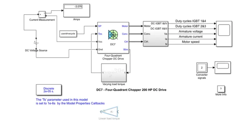
3>>Ans: The model of an Electric vehicle is built as shown in the below image :
EXPLANATION:
- In the above model of creating the electric vehicle model using DC7 or Four quadrant chopper DC drive, we are using a direct DV voltage Source.
- To measure the current flowing from the voltage source current measurement sensors is attached to the voltage source.
- The reference for the speed is given as input to the chopper block.
- The chopper block is then connected to the IGTB transistor.
- This IGTB is connected to the scope and all the results will be plotted in the scope for reference.
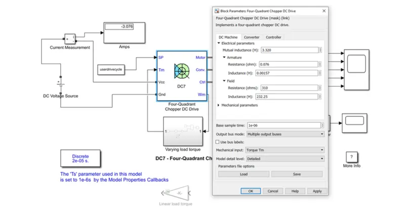
Inside the chopper drive, there will be inputs and outputs which are DC motor, Converter, Controller.
OUTPUT:
- According to the given inputs as drive cycle, angular speed data and a DC Voltage the plots were displayed in the scope.
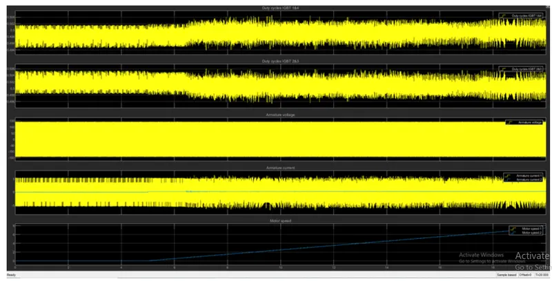
- According to the given input angular speed up to 5 sec the motor speed is near 0 and after 5 sec the motor sped is started to increase gradually where the simulation time is set to 20 seconds.
- The maximum duty for IGBT 1 & 4 , 2 & 3 is about 51%.
- The Armature Voltage is up to 150v and the armature current is varied from -5 to +5.
CONCLUSION: We have successfully reduced the shoot up of armature current in the model of speed control of DC motor using BJT H Bridge. Compared the variation between the H Bridge model and four-quadrant chopper DC Drive (DC7). Successfully changed the drive and the motor torque characteristics in the DC7 model.