Project-1: Powertrain for aircraft in runways
1>>Ans: The aircraft's gross weight is the total aircraft weight at any moment during the flight or ground operation. An aircraft's gross weight will decrease during a flight due to fuel and oil consumption. An aircraft's gross weight may also vary during a flight due to payload dropping or in-flight fueling. At the moment of releasing its brakes, the gross weight of an aircraft is equal to its takeoff weight. During the flight, an aircraft's gross weight is referred to as the router weight or inflight weight. An aircraft's structure weight capability is typically a function of when the aircraft was manufactured and in some cases old aircraft can have their structural weight capability increased by structural modification.
- Maximum Design Taxi Weight(MDTW): The MDTW is the maximum weight certificated for aircraft maneuvering on the ground as limited by aircraft strength and airworthiness requirements.
- Maximum Design Takeoff Weight (MDTOW): is the maximum certificated design weight when the brakes are released for takeoff and is the greatest weight for which compliance with the relevant structural and engineering requirement has been demonstrated by the manufactures.
- Maximum Design Landing Weight(MDLW): The maximum certificated weight at which the aircraft meets the appropriate landing certification requirement. It generally depends on the landing gear strength or the landing impact loads on certain parts of the wing structure. The MDLW must not exceed the MDTOW. The maximum landing weight is typically designed for 10 feet per second sink rate at a touch down with no structural damage.
- Maximum Design Zero Fuel(MDZFW): The maximum certification design weight of the aircraft less all usable fuel and other specified usable agents. It is the maximum weight permitted before usable fuel and other specified usable fluids are loaded in specified sections of the airplane. The MDZFW is limited by the strength and airworthiness requirements. At this weight, the subsequent addition of fuel will not result in the aircraft design strength being exceeded. The weight difference between the MDTOW and the MDZFW may be utilized only for the addition of fuel.
- Minimum Flight Weight(MFW): minimum certificated weight for flight as limited by aircraft strength and airworthiness. In order to design an electric towing tractor, we need to know their load operating conditions so the weights of various types of aircraft are shown below. The total weight of an aircraft includes the aircraft's empty weight and payload.
Aircraft's empty weight: The aircraft's weight with leftover fuel in the tank with engine oil and other operating fluids.
Payload: The fuel weight with passengers weight and luggage weight
Here to design an electric-powered towing tractor we are considering it to work in extreme load conditions. So some of the heaviest aircraft are listed below:
- The Antonov An-225 Mriya is a cargo aircraft that was designed by the Antonov design bureau in Ukraine It is the heaviest aircraft ever built with a maximum takeoff load of 640 tonnes.
- The Airbus A380 is a widely used body aircraft manufactured by airbus. It is the world's largest passengers airline with a maximum takeoff load of 575 tonnes.
- The Boeing 747 -8 is a wide-body airline developed by Boeing commercial aircraft which is the latest variant of the 747 with a maximum takeoff load of 448 tonnes
- The Boeing717 is a domestic passengers aircraft that was designed to accommodate 130 passengers and its maximum take-off load is 55 tonnes.
- The Airbus A319 is a passengers aircraft manufactured by airbus it can accommodate up to 150 passengers and its maximum takeoff load is 64 tonnes.
- The Embraer Phenom 300 is a private jet developed by Embraer a Brazillian manufacturer, which can take 11 passengers with a maximum takeoff load of 8 tonnes.
2>>Ans: As mentioned above in the question true airspeed is simply the speed at which an aircraft is moving relative to the air it is flying. AS such it's also the speed at which the air is flowing around the aircraft's wings. Ground speed on the other hand is the aircraft's speed relative to the ground. One thing that should be noted here is that it's horizontal rather than vertical speed an aircraft climbing completely vertically would have a ground speed of zero. In other words, while airspeed is what determines whether there is enough airflow around aircraft to make it fly, ground speed is what determines how fast an aircraft will get to its destination.
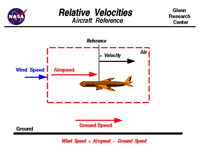
- The aircraft usually operates inland as well as in air so we need to study their speed differences in-ground and in air
- The ground speed and the airspeed usually change based on the wind components
- if we consider that there is no wind component then ground speed equals airspeed
- if the wind is blowing in the tail direction of the aircraft then airspeed is greater than ground speed so airspeed equals ground speed and wind components
- if the wind is blowing in the head direction of the aircraft then airspeed is less than ground speed so airspeed is equaled to ground speed minus the wind components
- Also, gravity plays a major role in increasing the aircraft's speed while it is decreasing.
3>> Ans: Taxing is the movement of an aircraft on the ground under its own power in contrast to towing or pushback where the aircraft is moved by a tug. The aircraft usually moves on wheels but the terms also include aircraft with skis or floats. The aircraft usually does not use its engine powered to reach the runway from the airport terminal. This happens because when the aircraft engine power is used the propeller blades start rotating and it eventually pulls the dust and other particles on the ground into the propeller and which can damage the propeller blades. Also, there are other reasons like propeller will cause a lot of wind disturbances around the aircraft which will be a problem for the nearby buildings and other aircraft settled nearby. So to avoid all these towing tractors are introduced for getting the job done. An airplane uses taxiways to taxi from one place on an airport to another for example when moving from hunger to the runway, the terms taxing is not used for the accelerating run along with a runway prior to takeoff or the decelerating run immediately after landing which are called the takeoff roll and landing rollout, respectively. it is not recommended for an aircraft to use its engine power as most aircraft have jet propulsion engines using gas turbines. An average A320 aircraft can produce up to 105KN of thrust. This is enough to burn a small populated village if the combustion goes unburnt to the turbine and hence creating flames outside the engine. Another reason is that the jet engines used in aircraft blast a lot of flames once combustion starts. When taxing aircraft travel slowly, this ensures that they can be stopped quickly and do not risk wheel damage on larger aircraft if they accidentally turn off the paved surface, taxi speed is typically 30 to 35 km/h. The use of engine thrust near the terminal is restricted due to the possibility of jet blast damage.
4>> Ans: Taxing refers to the movement of an aircraft on the ground under its own power. The aircraft moves on wheels. An airplane uses taxiways to taxi from one place of an airport to another. for example when moving from a terminal to the runway.
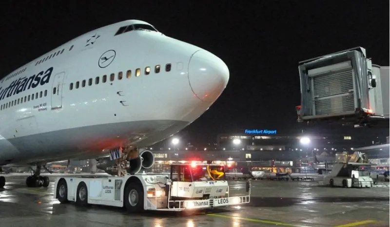
When aircraft is ready with all passengers and luggage the aviation pushback is an airport procedure during which an aircraft is pushed backward away from an airport gate by an external power. The aircraft always moves on the ground following the yellow lines, to avoid any collision with the surrounding vehicle and other aircraft. The taxing motion has a speed limit. Before making a turn the pilot reduces the speed further to prevent tire skids. Just like cars, there is a certain list of priorities during taxiing. The aircraft that are landing or taking off have higher priority. the other aircraft have to wait for these aircraft before they start or continue taxiing. The thrust to propel the aircraft forward comes from its propellers or jet engines. Steering is achieved by turning a nose wheel or tail wheel under or rudder, the pilot controlling the direction traveled with their feet. The use of engine thrust near terminals is restricted due to the possibility of jet blast damage. This is why the aircraft is pushed back from the buildings by a vehicle before they can start their own engines for taxing.
- pushback is carried out by special low profile vehicles called pushback tractors or tugs
- These are heavy weighing low profile vehicles with enormous torque to do the job of pushing or pulling the large aircraft from the terminals to the runway
- The tractors are designed with extra weight purposely to offer them enough traction to push or pull heavy aircraft.
5>>Ans: a) Take Off Power: Takeoff is the phase of flight in which an aerospace vehicle leaves the ground and becomes airborne. For aircraft that take off horizontally, this usually involves starting with a transition from moving along the ground on a runway. The takeoff speed required varies with air density, aircraft gross weight, and aircraft configuration. The power from the engine of the aircraft used to achieve the flight is called takeoff power. For light aircraft, usually, full power is used during takeoff. Large transport category aircraft may use a reduced power for takeoff, where less than full power is applied in order to prolong engine life, reduce maintenance and reduce noise emissions.
b) Tyre Design: The aircraft tire is usually specially designed as the tire has to withstand more load and also the higher speed at the same time. The number of tires required for any aircraft increases with the aircraft's weight, as the weight of the aircraft needs to be distributed more evenly. The aircraft's tread pattern is designed to facilities stability in high crosswind conditions, to channel water away to prevent hydroplaning and for braking effect, some of the tire designs are listed below:
Bias Ply Tyre: The bias ply tire consists of casing piles running diagonally at approximated right angles to one another. The number of piles and the angles at which they are laid dictate strength and load capacity. High-performance bias aircraft tires feature inter tread reinforcing fabric. this provides additional high-speed stability, reduces tread distortion under load, protects the casing piles from damage, and can act as wear indicators on retread able tires. The figure is as shown below:
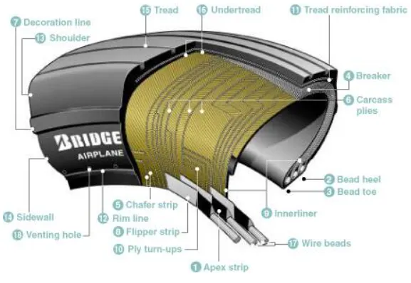
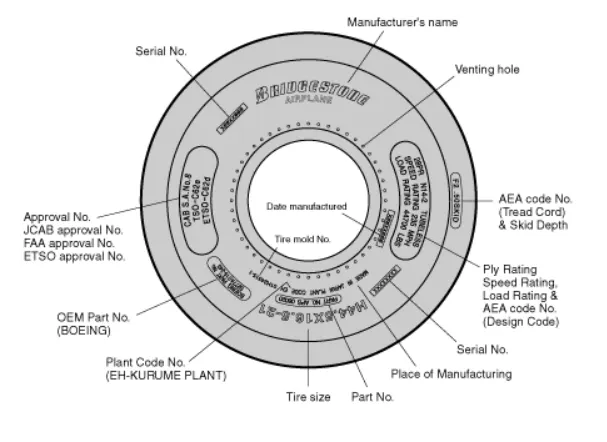
Tire Terminology :
1) Apex Strip: A triangular piece of stiff rubber that is fitted onto the bead core to taper the rigid bead into the flexible body piles in the sidewall.
2) Bead Heel: Outer edge of the bead.
3) Bead Toe: Inner edge of the bead
4)Breaker: Breakers are fabric plies placed directly on the uppermost ply beneath the tread rubber. They disperse stress throughout the tire. This breaker is utilized in a limited number of Bridgestone aircraft tires.
5) Chafer Strip: Reinforces the bead and protects the cord body plies from damage from rim friction or from damage when replacing the rim.
6)Carcass Plies: Each nylon ply is held by wire beads across the tire to keep tensile strength at the proper level and is folded to the side of the sidewall. Each ply is provided with cushion rubber to reduce the shearing forces produced between the cords of the tire when it is deformed. Multiple coated nylon cords are crossed alternately on the basis to make the carcass.
7) Decoration line: A projecting embossed line molded between the shoulder and sidewall of a tire. Its purpose is for decoration only.
8) Flipper Strip: A strip of material which is wrapped around the bead bundle and filter to add support and help the assembly into the sidewall.
9)Inner Liner: A special sheet which is made of rubber laminated to the inside of the first casing ply of the tubeless tire so as to ensure retention of pressure when the tire is inflated.
10) Ply Turn Ups: The turned-up ends of piles around the bead, other plies lock the ends into place.
11) Tread reinforcing Fabric: Nylon cord plies located in the tread groove and the outer ply of the carcass which reduce tread squirm and increase stability for high-speed operations.
12) Rim Line: This line is provided near the beads to allow inspection of how the tire fits with the rim.
13) Shoulder: The area on the side of the tire between the sidewall and the tread.
14)Sidewall: The side area of the tire located between the buttress and the beads. Composed of rubber it protects the carcass from damage.
15)Tread: A layer of rubber on the outer circumference of a tire, its major functions are to protect the casing from the cuts, withstand high speed during takeoff and landing provide traction, resist wear, provide durability under a wide range of temperature and to ensure stability. The tread compound is designed to suit a wide range of operations.
16) Under Tread: A rubber layer is provided for use in retreading the tire and which provides adhesion of tread to the cord body. Bridgestones make this rubber layer thick enough to ensure a high number of retreads.
17)Wire Beads: Constructed of steel wire encased in rubber they help to maintain the shape of the tire and keep it securely fixed to the rim, the wire beads are wrapped with fabric.
18) Venting Hole: The hole through which gas is vented from inside the carcass plies.
Balance Marker: A balance marker consisting of a red dot is affixed on the sidewall of the tire immediately above the bead to indicate the lightweight points of the tire.
Radial Tyre: Radial tires are the most modern design of aircraft tires. It is designed that is similar to that of a car tire. Typically the radial tire offers more landing per tread and lighter weight than a bias tire, though sometimes at the expense of retread lives, Radial aircraft tires differ from bias aircraft tires in that the piles all run radially from bead to bead at approximately 90" to the centerline of the tire. Angled belt piles are laid between the tread and the top casing ply, resulting in a flatter tread and adding strength to the tire.
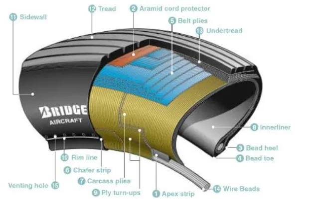
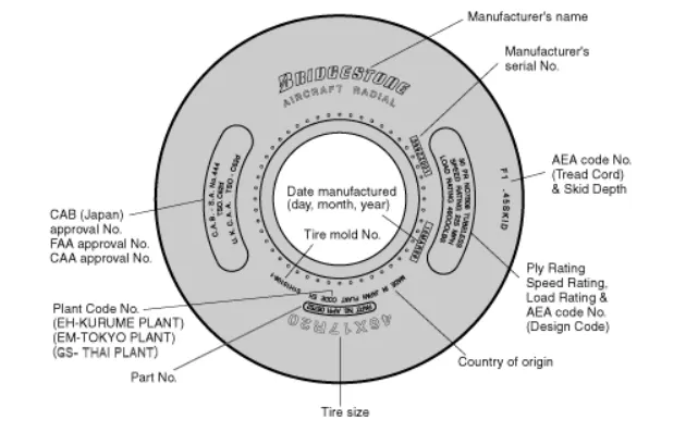
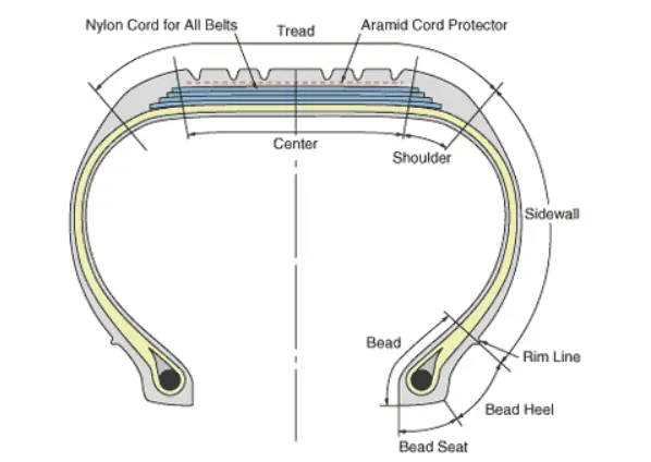
Tire Terminology:
1)Apex Strip: A triangular piece of stiff rubber which is fitted onto the bead core to taper the rigid bead into the flexible body plies in the sidewall.
2) Aramid Cord Protector: The tire is constructed with an aramid ply insert between the tread and the top belt to prevent damage to the tire belts.
3)Bead Heel: Outer edge of the bead
4)Bead Toe: Inner Edge of the bead
5)Belt Plies: Angled belt plies serve to add strength to the tire especially in the tread area.
6)Chafer Strip: Protective layer of rubber and fabric which prevents chafing between cord body plies and the wheel.
7)Carcass Plies: Layers of rubber-coated fabric plies which have the cords running radially from bead to bead. These provide the tire with strength in the sidewall area
8) Inner Liner: A sheet of low permeable rubber laminated to the inside of the first casing of a tubeless tire to insure retention of air when the tire is inflated.
9) Ply Turn Ups: The turned-up ends of plies around the bead, other plies lock the ends into place.
10) Rim Line: A-line provided near the beads to allow inspection of how the tire fits with the rim
11) Sidewall: The side area of the tire located between the shoulder and the beads, composed of rubber, protects the carcass from damage.
12) Treas: The main function of the radial tread are the same as those defined for the bias tire.
13)Under Tread: A rubber layer is provided for use in retreading the tire and which provides adhesion of tread to the tire carcass. Bridgestone makes this rubber layer thick enough to ensure a high number of retreads.
14)Wire Beads: Two-wire bundles which help to maintain the shape of the tire and anchor it securely to the rim.
15) Venting Hole: The hole through which gas is vented from inside the carcass plies.
Balance Makers: A balance marker consisting of a red dot is affixed on the sidewall of the tire immediately above the bead to indicate the lightweight point of the time.
Rolling Resistance: The rolling resistance force is mainly experienced by the tire when the vehicle moves over any surface. Thre rolling resistance force is given by the expression: Frr = urr * (m*g)
where, m*g is weight in newtons
urr=coefficient of rolling resistance
The coefficient of rolling resistance depends on many factors like temperature, tire temperature, the material of the tire, threaded pattern of the tire, and also the road roughness and liquid on the road. These factors determine the rolling resistance force.
Tyre pressure: The pressure generally is very high in an aircraft time to reduce the rolling resistance and to withstand the weight, usually, it will be around 200 to 300psi of pressure and they change based on the type of the aircraft. Tests of airliner aircraft tires have shown that they are able to sustain the pressure of a maximum of 800 psi. Aircraft tires are usually inflated with nitrogen to minimize expansion and contraction from the extreme changes in the ambient temperature and pressure experienced during flight.
Brake Force While Landing:
Aircraft Disc Brakes: The aircraft has disc rotors in the landing gear which are used to break the wheels while touching the ground. These brakes are operated hydraulically or pneumatically.
Thrust Reversers: Thrust reverses allows thrust from the engines to be used to slow the aircraft. This is also very effective in bringing down the speed of the aircraft. By using a negative angle plane, we are turning the wind that is coming into the propeller to flow in the opposite direction
Air Brake: Air brake dedicated flight control surface that works by increasing the drag force, air brakes are designed to increasing drag while making little change to lift, resulting in a higher stall speed. These are some of the types of braking methods used to bring down the aircraft's speed while landing the flight.
Large Drouge Parachute: It is used by several former and current and civilian aircraft and in the space shuttle.
6>>Ans: 1) The force acting on the aircraft should be analyzed:
The force that will be involved in moving the aircraft with the towing tractor is studied and there are mainly two forces acting in these conditions, they are:
1) Rolling Resistance force: The Rolling resistance force is mainly experienced by the tire when the vehicle moves over any surface. the rolling resistance force is given by the expression, Frr=Urr*(m*g)
where, m*g is weight in newtons
urr=coefficient of rolling resistance
The coefficient of rolling resistance depends on many factors like temperature, tire temperature, the material of the tire, threaded pattern of the tire, and also the road roughness and liquid on the road.
Here we are taking the heaviest flight as a reference to design our electric powered towing tractor because if we design for heavy application all the light aircraft can be push or pulled too, calculations are as follows:
let us assume, Weight of the aircraft ( Airbus A-380)=575000kg
Rolling resistance coefficient of an aircraft tire (Urr)=0.004
Weight of the towing tractor=50000kg
Rolling resistance coefficient of towing vehicle=0.001
then, the Rolling resistance force of the tow tractor=(0.001*(50000*9.81))
Rolling resistance force of tow tractor=0.49KN
Rolling resistance force of Aircraft=(0.004*(575000*9.81))
Rolling resistance force of aircraft=22.56Kn
Therefore, the total rolling resistance force = Rolling Resistance force of aircraft + Towing tractor = 0.49 + 22.56
Therefore, The total Rolling Resistance Force = 23.05KN.
2) Air Drag Force: The air drag force is the force that occurs due to the air striking effect on the vehicle when it moves. the vehicle moves through an air medium of a particular density value with a certain speed, this causes the air to strike against the body of the vehicle and it causes a drag force on the vehicle.
The Aerodynamic Drag is given by the expressions:
Fad = (1/2*rho*A*V*2c_d)
where,
rho = density of air medium
A= frontal area of the vehicle which strikes the air
v-velocity with which the vehicle moves
c_d=coefficient of drag which varies for different shapes of the frontal area.
The velocity of the aircraft while towing =30KMPH=8.33m/s
The density of Air Medium=1.225=rho
The frontal area of the Aircraft=20m^2
Coefficient of Drag Force=0.026
Air Drag Force=0.5*1.225*20*8.33^2*0.026 = 0.022KN
The Air Drag Force Acting=0.022KN
Therefore, the total force that the motor needs to overcome = Rolling resistance of the aircraft + Drag force acting on the aircraft hence the total forces acting = 23.05 + 0. 022
The Total Force that the motor needs to overcome in order to push or pull the aircraft = 23.07KN
The power required by the motor is given by the velocity with which the towing operations takes place, the average speed of the push or pull = 20kmph = 5.5m/s
Power required by the mootr = total force * velocity = 23.07 * 5.5
Power required by the mootr = 126.8Kw
The torque output of the towing tractor can also be calculated by the below steps:
Fte = (T*G)/(r)
where Fte= the total tractive force
T= Torque output
r=radius of tire
G=gear ratio
for a heavy-duty towing tractor, we assume, G=11,r=25inches=0.635m,
T=(23000*0.635)/11
The Torque required to push or pull, for the above-stated condition = 1.327KNm
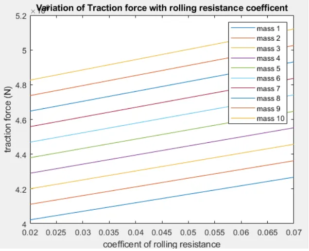
The program for the above is as shown below:
clc;
clear all;
close all;
Urr=[0.02,0.03,0.04,0.05,0.06,0.07];
u=0.8
m=linspace(500000,600000,10);
g=9.81;
rho=1.25;
A=158.3;
cd=0.02;
v=3;
r=0.35;
G=20;
frr=zeros(6,10);
fad=zeros(6,10);
ffr=zeros(6,10);
fte=zeros(6,10);
for (i=1:6)
{
for(j=1:10)
frr1=urr(i).*m(j)*g;
frr(i,j)=frr1;
fad1=0.5*rho*A*cd*v^2;
fad(i,j)=fad1;
ffr1=u*m(j).*g;
ffr(i,j)=ffr1;
fte(i,j) = frr(i,j)+fad(i,j)+ffr(i,j);
end
end
p=(fte.*v)/1000;
T=(fte.*r)/G;
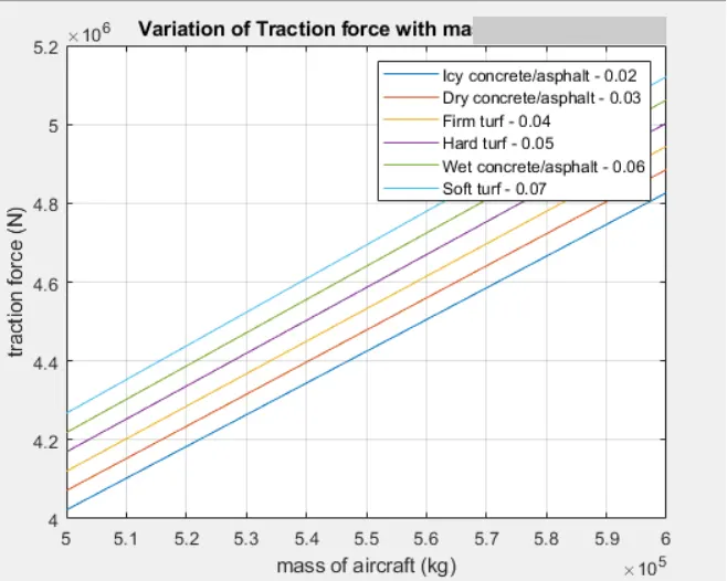
Plot(m,fte)
xlabel('mass of aircraft (kg)')
ylabel('traction force(N)')
title('Varation of Traction force with mass of aircraft');
legend("Icy concrete/asphalt = 0.02", Dry concrete/asphalt - 0.03", Firm turf-0.04",Hard truf-0)
grid on;
plot(urr,fte)
xlabel('coefficient of rolling resistance');
ylabel('traction force(N)');
title('Variation of traction force with rolling resistance coefficient');
legend("mass 1","mass 2", "mass 3","mass 4","mass 5","mass 6 ","mass 7","mass 8 ","mass 9","mass 10",);
7>>Ans: Assumptions: for doing this problem, i have considered the values related to aircraft like
aircraft weight=31298kg
towing tractor=1100kg
coefficient of drag=0.02
coefficient of rolling resistance=0.03
frontal area=158.3sqm
rolling resistance coefficient=0.03
velocity=10km/hr=3m/sec
power=19000 pound-force=84.516KN=84516.21N
towing tractors wheel radius=0.35m
gear ratio=20
velocity = 10km/hr=3m/sec
Density of air = 1.25kg/m^3
Acceleration of gravity = 9.81m/sec^2
Advisor tool to design the motor ratings
Type of motor and motor power ratings:
For motor specifications and rating:
Motor Model-MC_AC30, Siemens AC 30KW induction motor / controller
Maximum Power = 250KW
Efficiency=86%
Mass of Motor=58kg
Voltage=216v
Peak Current=280A
Minimum Voltage=140V
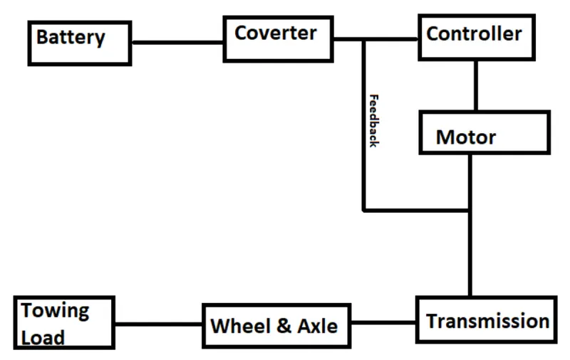
The figure of powertrain for aircraft Towing Tractor is as follows:
Now let us look at the program to calculate the traction force required for towing the aircraft using the above-defined motor ratings are as shown below:
clc;
clear all;
close all;
urr=0.03;
u=0.2;
ma=31298;
mt=1100;
g=9.81;
rho=1.25;
A=158.3;
cd=0.02;
v=3;
r=0.35;
G=20;
frr=urr*(ma+mt)*g;
fad=0.5*rho*A*cd*v^2;
ffr=u*(ma+mt)*g;
Traction _force_in_N = (frr+fad+ffr)
output :
traction _force_in_N = 7.3117e+04
Power_Kw=219.3522
Thus, the power required to pull the aircraft and the towing tractor will be 219.3522KW, and the selected motor's power rating is 250KW, which becomes the input power required by the motor. Hence the duty cycle range is calculated by finding the ratio of output to input power that is Pout/Pin = 19.35/25=0.8774
So we can say the duty cycle range is from 0 to 87.74%.
Now, we can assume that the tractor takes 10minutes or 60 seconds to tax. Hence the energy required to fulfill aircraft towing application (E)=Pout * t
E=219.3522 * 600
E =131.611Mj
Results:
- The reference aircraft taken here is the Heavy Aircraft build and so our design towing tractor is a heavy-duty operational vehicle.
- The power requirements are calculated for the particular load to be pushed or pulled and to achieve this power at the motor output, the motor type and its voltage at the terminals are discussed
- Then the power converters are used to upscale the battery armature voltage to the desired high voltage value so that the motor may spin at full power and required torque can be achieved using a Bidirectional DC-DC Converters
- Finally, the speed control of the vehicle is done with the switching technique where the duty cycle adjustment can change the motor speed from minimum to maximum.