Week-7 Challenge: DC Motor Control
AIM: To Control the Speed of a DC motor using BJT H-bridge.
Choppers
The chopper is a static device that converts fixed DC voltage to an adjustable (Variable) dc output voltage directly.
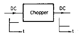
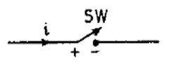
Figure 1 &2 represents the chopper circuit diagram and chopper switch
The power semiconductor devices used for a chopper circuit can be power BJT, power MOSFET, GTO or force-commutated thyristors. This device can be represented by a switch SW fig (2). when the switch is ON the current flows through circuit and SW is OFF no current can flow.
Principle of Chopper Operation:
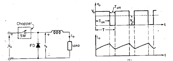
Figure 1 shows that the chopper circuit and figure 2 shows output voltage and current waveforms.
A chopper is a high speed ON/OFF semiconductor switch. It connects source to load and disconnects from load to source at a fast speed. The chopper represented by a switch SW inside the dotted rectangle box as shown in fig(1).
During the Period Ton Chopper is ON and load voltage is equal to the source voltage Vs , During the Period Toff the chopper is off load current flows through the freewheeling Diode FD then the load terminals are short circuited by FD and load voltage is zero.
Vo = [Ton/Ton + Toff ]*Vs where Ton = ON Time, Toff = OFF Time
= [Ton/T]*Vs
Vo = Alpha * Vs
T = Ton + Toff = Chopping period
Alpha= Ton/T = Duty cycle
Vo = f* Ton* Vs
Chopping frequency (f) = 1/T.
Block diagram of DC motor using H-Bridge:
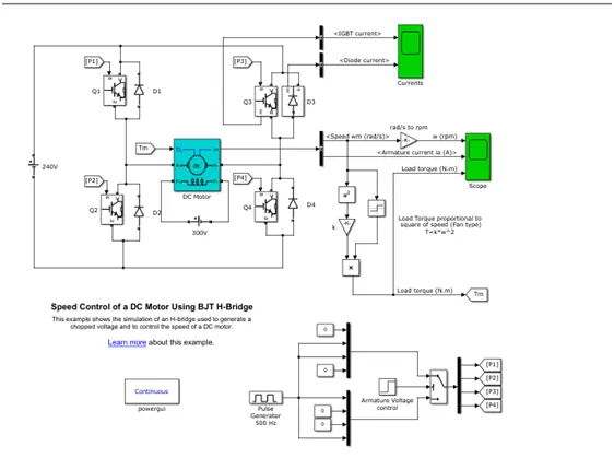
The above block diagram shows that the H-bridge circuit of a DC motor used to control the speed. The Bipolar Junction Transistor when used for power switching applications, operates as an IGBT. When it is conducting BJT is operating in the saturated region, a forward voltage Vf is developed between collector and emitter in the range of 1v. Therefore, the IGBT block can be used to model the BJT device. The DC motor use the preset model (5 HP 24V 1750 rpm). It simulates a fan type load where Load torque is proportional to square of speed. The armature mean voltage can be varied from 0 to 240 V when the duty cycle specified in the Pulse Generator block is varied from 0 to 100%.
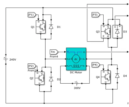
The chopper circuit is called 2-Quadrant chopper. This is not only operated in Acceleration mode/motoring mode but also operates in Regenerative and braking mode. The H-Bridge consists of four BJT/Diode pairs BJT simulated by IGBT models. Two transistors are switched simultaneously Q1 and Q4 or Q2 and Q3. When Q1 and Q4 are ON, a positive voltage is applied to the motor and diodes D2-D3 operate as free-wheeling diodes when Q1 and Q4 are switched off. When Q2 and Q3 are ON, a negative voltage is applied to the motor and diodes D1-D4 operate as free-wheeling diodes when Q2 and Q3 are switched off.
Results
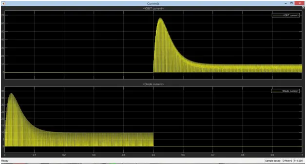
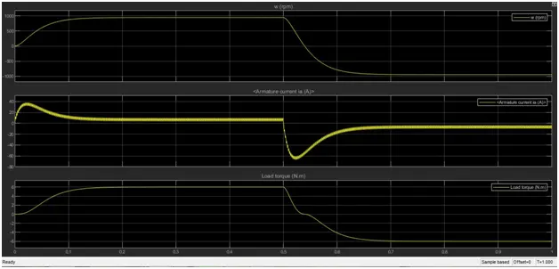
The motor starts in the positive direction with a duty cycle of 75% mean DC voltage of 180V. At t= 0.5 sec & the armature voltage is suddenly reversed and the motor runs in the negative direction. Figure 2 shows that the motor speed, armature current and load torque and Currents show currents flowing in BJT Q3 and diode D3.
1B. The armature current shoot-up from the scope results
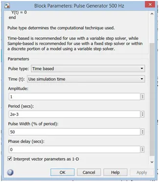
The duty cycle of the Pulse generator changes from 75% to 50%. The simulation results are given below.
 v
v
The above results show the diode current and the IGBT currents. The IGBT current is constant upto the 0.5 sec and after 0.5sec the currents increases to the maximum value and reduces gradually to certain value. The diode current is increases to maximum value when the diode is in conducting mode and reduces to zero in non conducting mode.
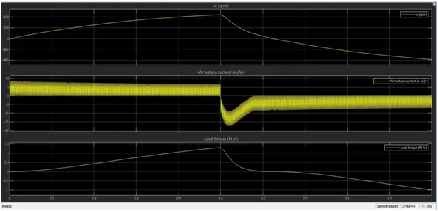
The above shows the speed torque characteristics and armature current ia . Here the Armature current ia is constant upto the 0.5sec and suddenly falls to negative direction due to the switching occurs in the circuit.
1C. The Four-Quadrant Chopper DC Drive (DC7) block
The Four Quadrant chopper consists of four semiconductor switches CH1 to CH4 and four diodes D1 to D4 in anti-parallel.
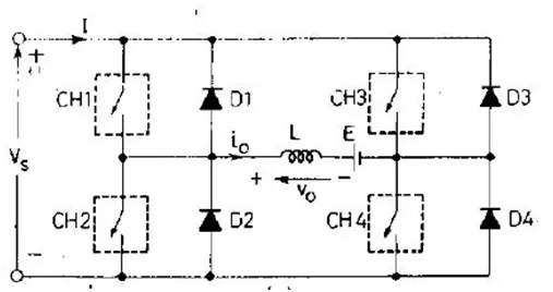
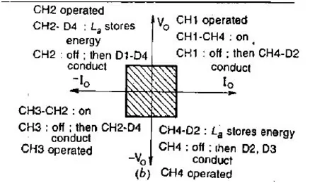
Figure 1 & 2 shows circuit diagram of four-quadrant chopper and conducting modes of operation.
Quadrant I:
CH4 is kept ON, CH3 is kept off and CH1 is operated CH1 & CH4 is ON the load voltage V0 = Vs and load current i0 begins to flow both Vo & io are positive giving first quadrant operation. When CH1 is turned OFF positive current freewheels through CH4, D2. This Quadrant is also known as Forward motoring.
Quadrant II:
CH2 is operated and CH1, CH3 & CH4 are kept OFF. CH2 ON reverse or negative current flows through L, CH2, D4 and E. inductance L stores the energy during the time CH2 is ON. The CH2 is turned OFF current is fed back to source through diodes D1, D4. As the load voltage Vo is positive and io is negative. This Quadrant is also known as Forward Braking.
Quadrant III:
CH1 is kept OFF, CH2 is ON and CH3 is operated. Polarity of load emf E must be reversed for this quadrant. CH3 is ON load gets connected to source voltage Vs so that both Vo & io are negative leading to the 3rd quadrant operation. When CH3 is turned OFF, the negative current freewheels through CH2, D4. This Quadrant is also known as Reverse motoring.
Quadrant IV:
CH4 is operated and remaining devices are kept OFF. Load emf E must have its polarity reversed for the 4th quadrant operation. When CH4 is ON the positive current flows through CH2,D2, L and E. inductance L stores energy during the time CH4 is ON. When the CH4 is OFF the current in the circuit is feedback to the sources through diodes D2, D3. The load voltage is negative, but load current is positive leading to the chopper operation. The power also feedback from load to source. This Quadrant is also known as Reverse Braking.
Simulation Block diagram Four-Quadrant Chopper DC Drive (DC7)
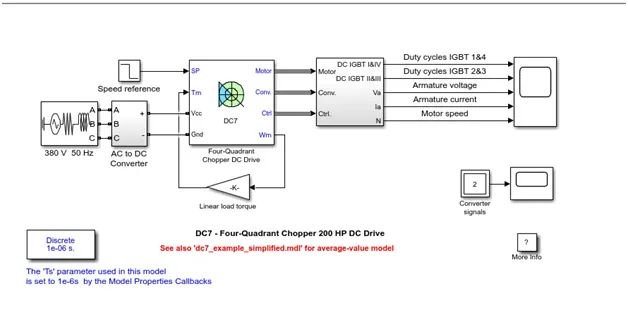
The armature voltage is provided by an IGBT converter controlled by an two PI (Proportional Integrator) Controllers. The converter is fed by a 515v DC bus obtained by rectification of a 380v AC 50Hz voltage source in order to limit the DC bus voltage during the dynamic braking mode, a braking chopper has been added between the diode rectifier and the DC7 block.
The first regulator is speed regulator, followed by a current regulator. The speed outputs the armature current reference used by the current controller is order to obtain the electromagnetic torque needed to reach the desired speed. The speed reference change rate follows acceleration and deceleration ramps in order to avoid sudden reference changes that could cause armature over-current and destabilize the system. The current regulator controls the armature current by computing the appropriate duty ratios of the 5kHz pulses of the four IGBT’s. For proper system behavior the instantaneous pulse values of IGBT devices 1 &4 are opposite to those of IGBT device 2 & 3. This generates the average armature voltage needed to obtain the desired armature current. In order to limit the amplitude of the current oscillations a smoothing inductance is placed in series with the armature circuit.
Comparison of Four-Quadrant Chopper DC Drive (DC7) with the H-bridge model:
Four-Quadrant Chopper:
It operates in Four Modes of operations ie., Forward Motoring, Forward Breaking, Reverse Motoring and Reverse Breaking. In electronics, a chopper circuit used in power control and signal applications used for DC motor control, solar energy conversion and wind energy conversion. It is also used in electric vehicles, airplanes and spaceships. Also used as power supplies in computer, commercial electronics, and electronics instruments.
H-bridge model:
H-bridge is an electronic circuit that switches the polarity of a voltage applied to a load. An H-bridge is built with four switches solid-state or mechanical. This condition is known as shoot-through. Modes of operations forwarding mode and reserving mode. These circuits are often used in robotics and other applications to allow DC motors to run forwards or backwards. The most important application of the H-Bridge circuit as the motor driver circuit. In Robotics Technology, H-bridge circuits are used. H-Bridge circuit is also used as Inverter circuit. In modern battery charger for electrical vehicles, H-bridge circuits are used.
2.Two-quadrant chopper
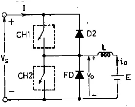
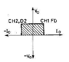
The output voltage V0 is always positive because of the presence of freewheeling diode FD across the load. When chopper CH2 is ON then freewheeling diode (FD) conducts output voltage V0 = 0 and chopper CH1 is ON then diode conducts output voltage V0 = Vs. The load current i0 is positive when CH1 is ON. Load currents is negative if CH2 is ON or D2 is conducts. The Average load voltage is always positive but average load current may be positive or negative. Therefore the power flow may be from source to load (1st quadrant operation) or from load to source (2nd quadrant operation). Chopper CH1 & CH2 should not be simultaneously because it leads to short circuit on the supply lines. This type of chopper configuration is used for motoring and regenerative braking of dc motors.
Simulink Block Diagram of 2 Quadrant DC Motor
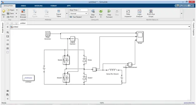
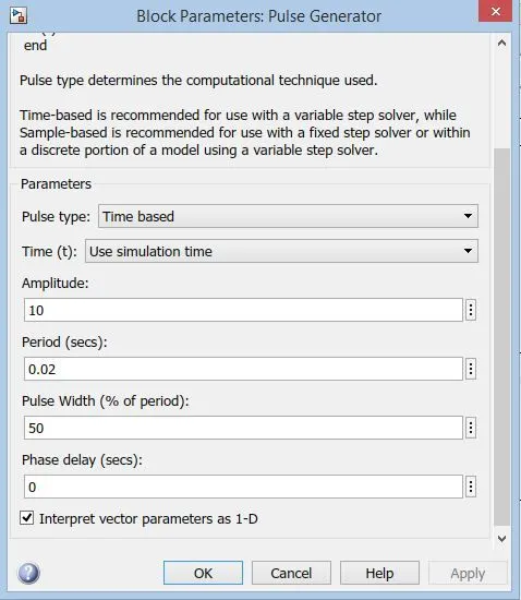
The Mosfet and Diode are connected to dc voltage source of 24v. Using the logical operations like NOT gate because the mosfet should not conducts simultaneously if both mosfet conducts simultaneously the supply will be short circuited. Load voltage source is 12v.
Results
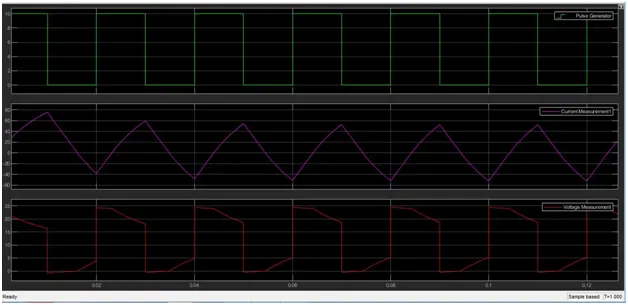
From the above results clearly observed that the voltage waveforms not going less than 0v that is minimum value is 0 and maximum value is always in the positive direction. The current increase and decrease and goes positive and negative values based on the switching action (freewheeling action takes place). Voltage is always positive and current is either be positive or negative.
3.Explain in a brief about operation of BLDC motor.
A motor converts supplied electrical energy into mechanical energy. Various types of motors are in common use. Among these, brushless DC motors (BLDC) feature high efficiency and excellent controllability, and are widely used in many applications. The BLDC motor has power-saving advantages relative to other motor types.
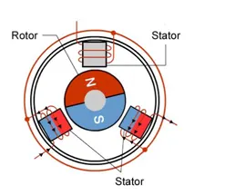
Construction
BLDC motors have many similarities to AC induction motors and brushed DC motors in terms of construction and working principles respectively. Like all other motors, BLDC motors also have a rotor and a stator
Stator
Similar to an Induction AC motor, the BLDC motor stator is made out of laminated steel stacked up to carry the windings. Windings in a stator can be arranged in two patterns; i.e. a star pattern (Y) or delta pattern (∆). The major difference between the two patterns is that the Y pattern gives high torque at low RPM and the ∆ pattern gives low torque at low RPM. This is because in the ∆ configuration, half of the voltage is applied across the winding that is not driven, thus increasing losses and, in turn, efficiency and torque.
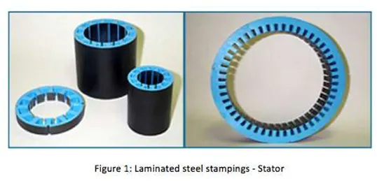
Steel laminations in the stator can be slotted or slot less as shown in Figure 2. A slot less core has lower inductance, thus it can run at very high speeds. Because of the absence of teeth in the lamination stack, requirements for the cogging torque also go down, thus making them an ideal fit for low speeds too (when permanent magnets on rotor and tooth on the stator align with each other then, because of the interaction between the two, an undesirable cogging torque develops and causes ripples in speed). The main disadvantage of a slot less core is higher cost because it requires more winding to compensate for the larger air gap.
Rotor
The rotor of a typical BLDC motor is made out of permanent magnets. Depending upon the application requirements, the number of poles in the rotor may vary. Increasing the number of poles does give better torque but at the cost of reducing the maximum possible speed.
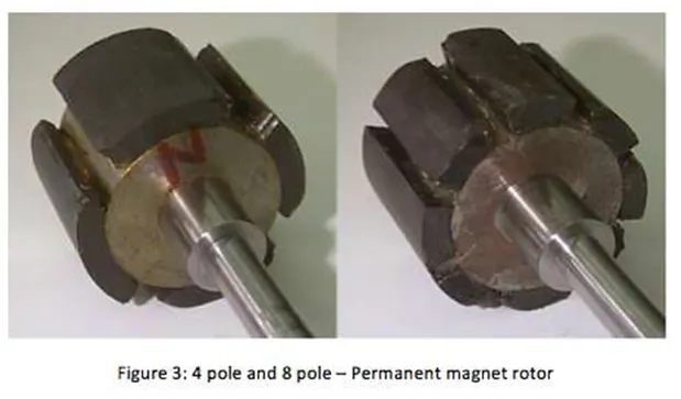
Another rotor parameter that impacts the maximum torque is the material used for the construction of permanent magnet; the higher the flux density of the material, the higher the torque.
Electrical equipment often has at least one motor used to rotate or displace an object from its initial position. There are a variety of motor types available in the market, including induction motors, servomotors, DC motors (brushed and brushless), etc. Depending upon the application requirements, a particular motor can be selected. However, a current trend is that most new designs are moving towards Brushless DC motors, popularly known as BLDC motors.
Working Principles and Operation
The underlying principles for the working of a BLDC motor are the same as for a brushed DC motor; i.e., internal shaft position feedback. In case of a brushed DC motor, feedback is implemented using a mechanical Commutator and brushes. With a in BLDC motor, it is achieved using multiple feedback sensors. The most commonly used sensors are hall sensors and optical encoders. Hall sensors work on the hall-effect principle that when a current-carrying conductor is exposed to the magnetic field, charge carriers experience a force based on the voltage developed across the two sides of the conductor. If the direction of the magnetic field is reversed, the voltage developed will reverse as well. For Hall-effect sensors used in BLDC motors, whenever rotor magnetic poles (N or S) pass near the hall sensor, they generate a HIGH or LOW level signal, which can be used to determine the position of the shaft.
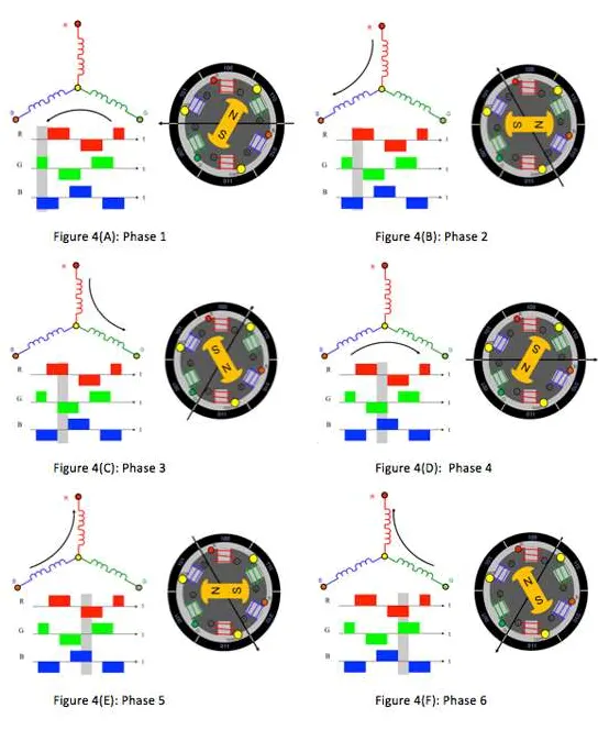
In a commutation system – one that is based on the position of the motor identified using feedback sensors – two of the three electrical windings are energized at a time as shown in figure 4 The Green winding labeled 001 is energized as the North pole and the Blue winding labeled as 010 is energized as the South pole. Because of this excitation, the South Pole of the rotor aligns with the Green winding and the North Pole aligns with the Red winding labeled “100”. In order to move the rotor, the “Red” and “Blue” windings are energized in the direction shown in figure 4(B). This causes the Red winding to become the North Pole and the BLUE winding to become the South Pole. This shifting of the magnetic field in the stator produces torque because of the development of repulsion (Red winding – North-North alignment) and attraction forces (Blue winding – North-South alignment), which moves the rotor in the clockwise direction.
Conclusion
controlling of speed of a dc motor has been run succuessfully.simulink of two quadrant dc motor
Executed and description of BLDC had discussed.