Week-7 Challenge: DC Motor Control
Question1 : Model of Speed control for a DC motor using BJT H-bridge
A) Explanation of the demo model
Step-1: To open the demo model type 'Speed control of a DC motor using BJT H-bridge' in matlab search documentation space
Step-2 : Press 'Open Model' tab, Fbelow given Model will open
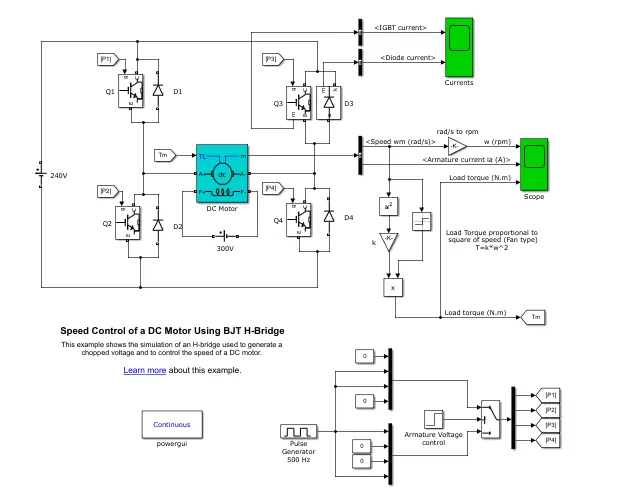
Step-3 : Follwing can be analysed from the model (Information source is Matlab Documetation)
*The Bipolar Junction Transistor (BJT) when used for power switching applications, operates as an IGBT.
*When it is conducting (BJT operating in the saturated region), a forward voltage Vf is developed between collector and emitter (in the range of 1 V). Therefore, the IGBT block can be used to model the BJT device.
*The IGBT block does not simulate the gate current controlling the BJT or IGBT. The switch is controlled by a Simulink signal (1/0). The DC motor uses the preset model (5 HP 24V 1750 rpm).
*It simulates a fan type load (where Load torque is proportional to square of speed). The armature mean voltage can be varied from 0 to 240 V when the duty cycle (specified in the Pulse Generator block) is varied from 0 to 100%.
The H-bridge consists of,
*Four BJT/Diode pairs (BJT simulated by IGBT models).
*Two transistors are switched simultaneously: Q1 and Q4 or Q2 and Q3.
*When Q1 and Q4 are fired, a positive voltage is applied to the motor and diodes D2-D3 operate as free-wheeling diodes when Q1 and Q4 are switched off.
*When Q2 and Q3 are fired, a negative voltage is applied to the motor and diodes D1-D4 operate as free-wheeling diodes when Q2 and Q3 are switched off.
Simulation
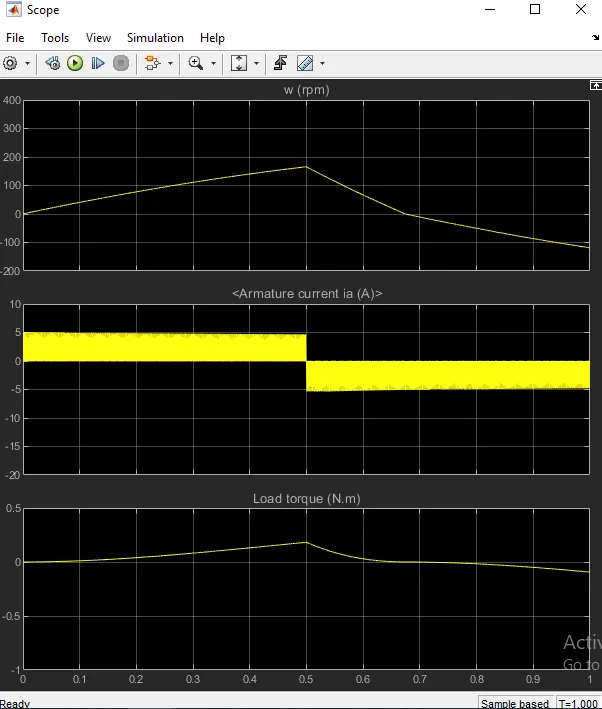
The motor starts in the positive direction with a duty cycle of 75% (mean DC voltage of 180V). At t= 0.5 sec., the armature voltage is suddenly reversed and the motor runs in the negative direction.
'Scope' shows motor speed, armature current and load torque and 'Currents' shows currents flowing in BJT Q3 and diode D3.
B) To Comment on the armature current shoot-up from the scope results.
Step-1: Run the above model and check the scope for results. Below graphs are observed
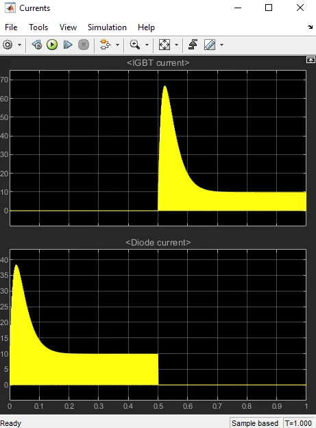
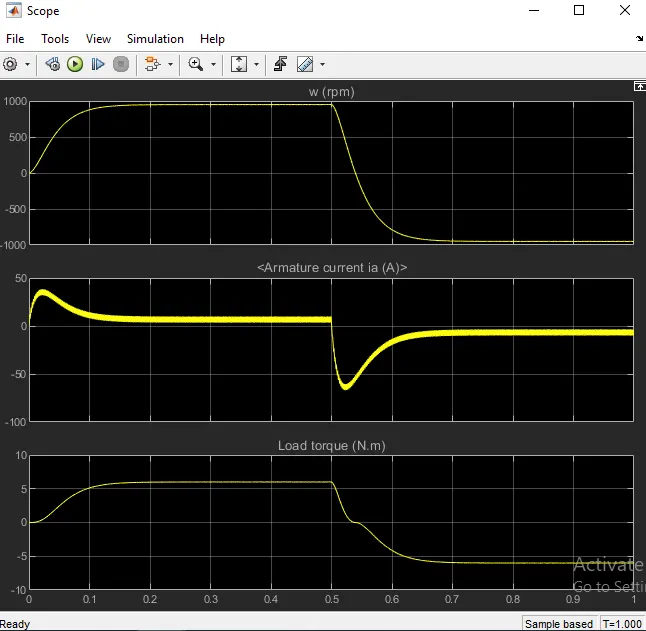
Observations :
- From the pulse generator it is noticed that pulse width is set as 0.75, which is 75% Duty Cycle
- Hence 0.75*240V = 180V DC voltage is supplied for motor positive direction motion
- At 0.5Sec Armature current reverses it's direction and motor runs in negative direction
- To avoid the initial spike of armature current , the duty cycle is changed from 75% to 50% in Pulse generator block and following graphs are seen (where armature current graph from 0 to 0.1sec is evident that initial spike is avoided at positive direction but stillexistes at negative direction)
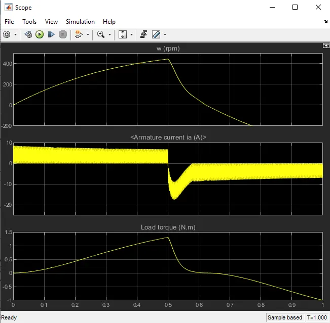
- To avoid negative spike the duty cycle is further reduced to 30% and from the below graph we can notice that negative spike is also avoided
C) Refer to the help section of ‘The Four-Quadrant Chopper DC Drive (DC7) block’. Compare it with the H-bridge model.
Step-1: open the The Four-Quadrant Chopper DC Drive (DC7) block from matlab documentation
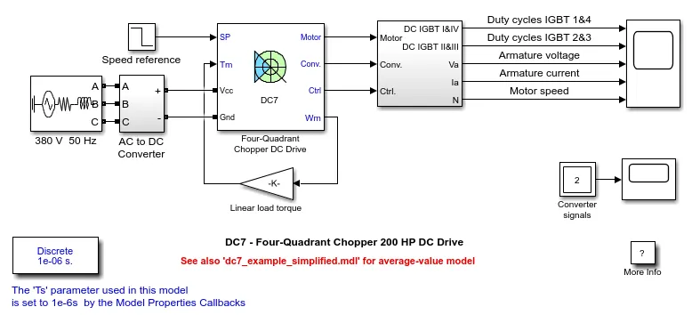
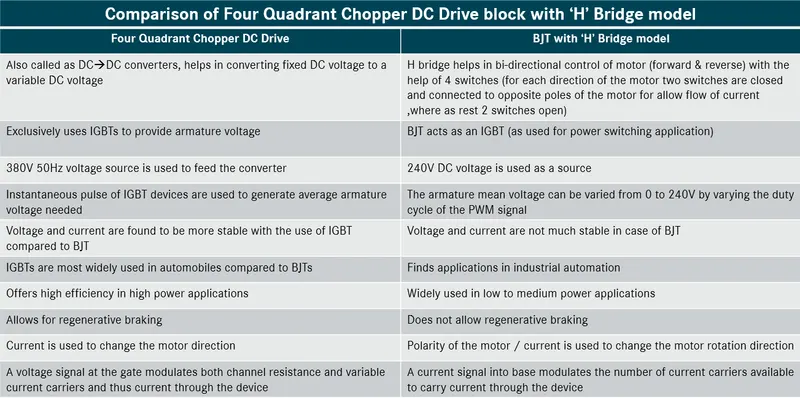
Step-2: After analysis and the comparison of the Four-Quadrant Chopper DC Drive (DC7) block with H-bridge model given in question-1. Following conclusions are arrived
Question2 : To Develop a 2-quadrant chopper using simulink & explain the working of the same with the relevant results.
From Matlab Documentation sources: The Two Quadrant chopper block represents a two quadrant controlled chopper for converting a fixed DC input to a variable DC output. the block contains 2 switching devices. The simscape model of the 2 quadrant chopper is given below (as given in matlab documentation)
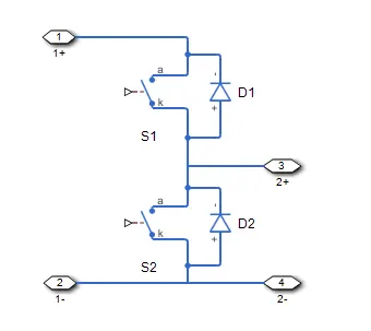
Simscape model of 2 quadrant chopper
-The block contains an integral protection diode for each switching device.
-The integral diode protects the semiconductor device by providing a conduction path for reverse current.
-An inductive load (Series RLC ckt) can produce a high reverse-voltage spike when the semiconductor device suddenly switches off the voltage supply to the load.
equivalnet circuit diagram for the above simscape is given below

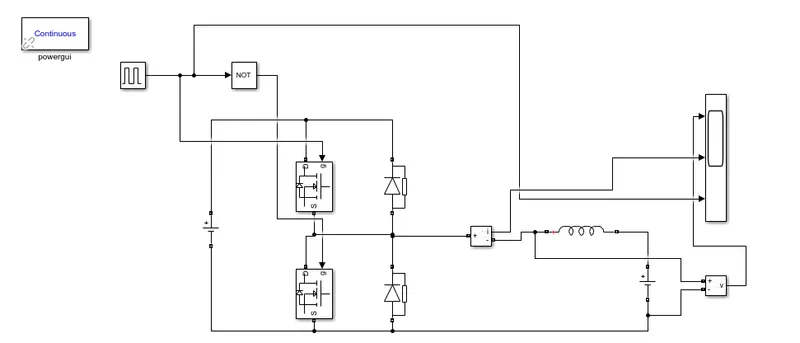
Simulink Model built to realize the 2 quadrant chopper is given below (also the simulinked model is attached with this submission)
Construnction Considerations:
DC voltage at input : 24V,
Pulse generator adjustments : Amplitude = 10, Pulse = 0.02sec, Pulse = 50%
Not gate added --> to manage only one switch active at a time and the other remains off
Only Inductor considered from series RLC circuit to ensure load
A current measurement and a voltage measurements are added for respective measurments at a give pulse
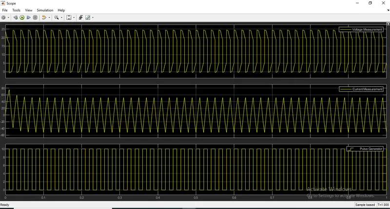
Finally the results of current measurments and voltage measurements for a given pulse at relative time intervals are observed from the scope and the graphs are given below the given simulink model
Observations and inference on 2 quadrant chopper
- Voltage always stays positive and minimum value is zero (never negative)
- Current goes both positive and negative
- Amplitude of the pulse remains 10
Question3 :
From the Matlab sources: Brushless DC motors makes use of a trapezoidal and field oriented control for it's operation depending on the application of it's use. Trapezoidal control uses only two phases at any give time and a PID controller to control the torque. Where as field oriented control seems complex compared to trapezoidal w.r.t construction and operation requirements.
In order to make the operation of the motor more reliable, more efficient and less noisy Brushelss DC motors have found a place in recent trends. These motors are less heavier compared to other motor with same power output. The brushelss DC motors are effective in offering extended life time of the motor and it's arrangment.
Construction and Workind Principle of Brushless DC Motor
The operation of the BLDC is simply based on the interaction of the force between the permanent magnet and the electro magnet. BLDC motor works on the principle similar to that of a conventional DC motor, i.e., the Lorentz force law which states that whenever a current carrying conductor placed in a magnetic field it experiences a force. As a consequence of reaction force, the magnet will experience an equal and opposite force. In case BLDC motor, the current carrying conductor is stationary while the permanent magnet moves
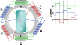
Brushless DC Motor arrangment and its switching sequence as given above
When the stator coils are electrically switched by a supply source, it becomes electromagnet and starts producing the uniform field in the air gap. Though the source of supply is DC, switching makes to generate an AC voltage waveform with trapezoidal shape. Due to the force of interaction between electromagnet stator and permanent magnet rotor, the rotor continues to rotate.
With the switching of windings as High and Low signals, corresponding winding energized as North and South poles. The permanent magnet rotor with North and South poles align with stator poles causing motor to rotate.
The motor produces torque because of the development of attraction forces (when North-South or South-North alignment) and repulsion forces (when North-North or South-South alignment). By this way motor moves in a clockwise direction.
The motor continuous rotation depends on the switching sequence around the coils.
Based on this signal from sensor, the controller decides particular coils to energize. Hall-effect sensors generate Low and High level signals whenever rotor poles pass near to it. These signals determine the position of the shaft.
BLDC motor has several advantages over conventional DC motors and some are given below
- No mechanical commutator and associated problems
- High efficiency due to the use of permanent magnet rotor
- High speed of operation even in loaded and unloaded conditions due to the absence of brushes that limits the speed
- Smaller motor geometry and lighter in weight than both brushed type DC and induction AC motors
- Long life as no inspection and maintenance is required for commutator system
- Higher dynamic response due to low inertia and carrying windings in the stator
- Less electromagnetic interference
- Quite operation (or low noise) due to absence of brushes
Applicaions of BLDCs
- Computer hard drives and DVD/CD players
- Electric vehicles, hybrid vehicles, and electric bicycles
- Industrial robots, CNC machine tools, and simple belt driven systems
- Washing machines, compressors and dryers
- Fans, pumps and blowers