Project-1: Powertrain for aircraft in runways
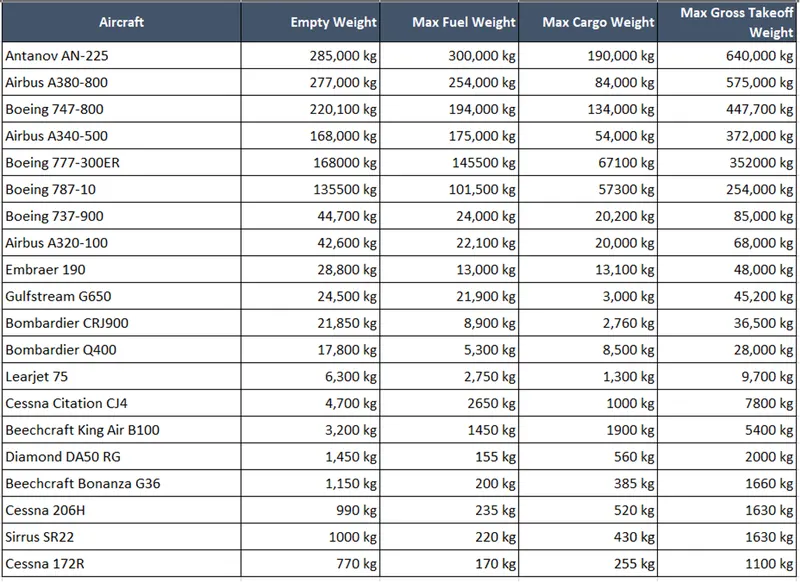
1. Search and list out the total weights of various types of aircrafts
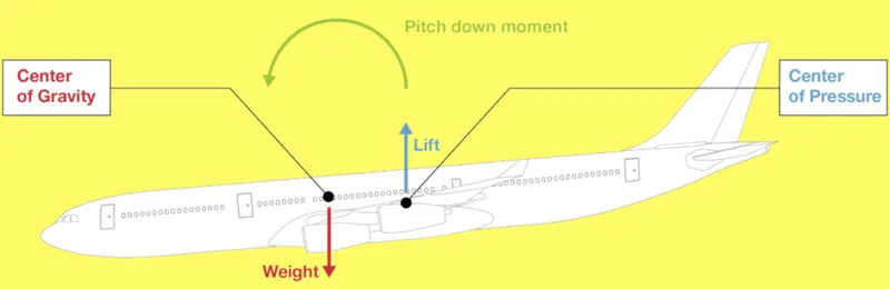
In order to well understand the impact of weight and balance on the stability and maneuverability of the aircraft, it is worth getting back to the forces that apply to the aircraft, and more specifically to focus on the vertical ones.
There are two of them, applying at distinct points along the aircraft longitudinal axis.
-The Weight of the aircraft, applied at the Center of Gravity (CG) of the aircraft.
- The Lift, applied at the Center of Pressure (CP).
The CG is further forward than the CP for aircraft stability reasons. Thus, the more distant the two points, the bigger the pitch-down moment.
Keeping the CG within the operational envelope is a must for safe flight as it will impact
-Aircraft maneuverability at all phases of flight
-Impact on aircraft performance at all phases of flight
-Impact on aircraft structure at take-off
-Impact on aircraft controllability at ground and take off
Hence, as an initial step list of total weights of various types of aircraft are collected from available sources
2. Difference between the ground speed and air speed.
Phenomenon of Air speed and the Ground speed is given in the below image
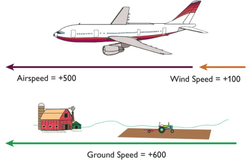
By the analysis of this image the key differences are mentioned in the below table.

3. Why is it not recommended to use aircraft engine power to move it on the ground at airport?
There is always a chance of moving an aircraft in reverse direction with the help of reverse thrust. But, there are certain reasons for not using this reverse thrust mechanism to move it on the ground at airports.
- Excessive use of fuel leading to noise, unpleasantness and possibly hazard for ground crew
- It is prudent to use only the amount of power to get the airplane moving and then reduce the power for taxiing to avoid high volumes of air spreading debris or damaging other aircraft or ground vehicles.
- Only aircraft with engines on the tail can still power-back due to FOD. Sometimes, if it’s a tight area, a tug will be used.
- It’s more expensive, not every ground crew is certified to start or taxi the aircraft. Hence, a tow vehicle is safer, easy to certify ground crews to hook up and tow and the un started engine is safer.
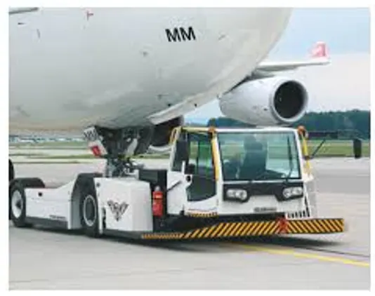
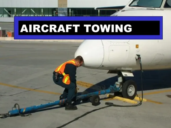
4. How an aircraft is pushed to runway when it is ready to takeoff?
An aircraft is usually brought back to runway by 'pushbak' mechanism.Pushback is when an aircraft is pushed backwards away from the airport gate by vehicles called tugs or tractors.Closer to departure, an aircraft tug will park right in front of the nose wheel.The tug might be directly attached to the plane's nose gear with a tow bar, or could be a "wheel-lift" tug. These tugs cradle the nose gear, then lift it up before moving the plane. That gives the tug driver control over the plane's direction during pushback.New taxi technologies are appearing, like pilot-controlled tugs, and electric motors mounted to the plane's landing gear. Both promise to save fuel, and reduce airport noise.
5. Learn about the take-off power, tyre design, rolling resistance, tire pressure, brake force when landing
"Take Off power / performance can be predicted using a simple measure of the acceleration of the aircraft along the runway based on force equilibrium"
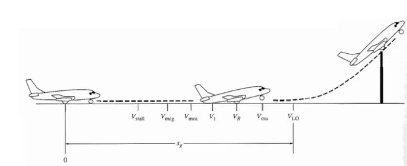
As the airplane accelerates from zero velocity, at some point it will reach the stalling velocity Vstall. The airplane continues to accelerate until it reaches the minimum control speed on the ground, Vmcg. This is the minimum velocity at which enough aerodynamic force can be generated on the vertical fin with rudder deflection while the airplane is still rolling along the ground to produce a yawing moment sufficient to counteract that produced when there is an engine failure for a multiengine aircraft. The forces involved will be ,
D - Aerodynamic drag of vehicle resisting the motion of aircraft
T - Propulsion thrust to move aircraft over runway
F - Friction of Rolling resistance offered by the wheels
W = weight of the aircraft
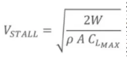
A = wing area
CL(max) - maximum achievable lift co-efficient
Vstall - lowest speed that an aircraft can be flown before the airflow starts to separate from wings.
Vstall can be calculate by using the below equation
" Tyre Design"
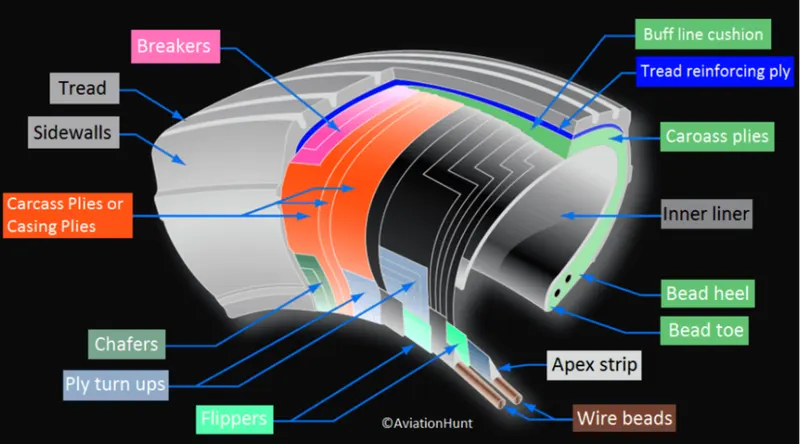
Carcass plies are used to form the tire. They are sometimes called casing plies. An aircraft tyre is constructed for the purpose it serves.
- They support the weight of an aircraft while it is on the ground.
- It also provides the necessary traction for braking and stopping of an aero plane.
- Tire also helps to absorb the shock of landing and provide cushioning the roughness of takeoff, roll-out, and taxi operations.
- Unlike an automobile or truck tire, it does not have to carry a load for a long period of continuous operation. However, an aircraft tire absorbs the high impact loads of landing, and also it’s operating at high speeds for a short time when required.
- The key technical prospects of a tire design are given below
- - Retreading – Retreading is methods of restoring a worn tire by renewing the tread area or by renewing the tread area plus one or both sidewalls. Repairs are included in the tyre retreading process.
- Load Rating – Load rating is the maximum permissible load at a specified inflation pressure.
- Ply Rating – Ply Rating is used to identify the maximum recommended load rating and inflation pressure for a specified tire. It is an index of tire strength.
- Speed Rating – The speed rating is the maximum takeoff speed to which the tire has been tested.
- Skid Depth – Skid depth is the distance between the tread surface and the deepest groove as measured in the mould.
- Aircraft tires must have an approved speed and load rating and have sufficient clearance when retracted through landing gear to allow for tire growth. Tire growth is the increase in the size of the tire due to centrifugal forces at high speed.
- Aircraft tires may be Tube-type or Tubeless: Tubeless tires are more advantageous over tube-type. There is no longer the use of tube-type tire in recent aviation. Nowadays all airliners are using tubeless tires. Tubeless that are meant to be used without a tube has the word TUBELESS on the sidewall of the tire.
- Aircraft tires may be Radial or Bias: Almost all airliners are using Radial tire. Bias is an older design, and it’s mainly used for road vehicles. Radial tires have the word RADIAL on the sidewall. Radial tires are more expensive than bias-ply tires. Radial tires are in demand because of their lower life cycle cost and long term value.
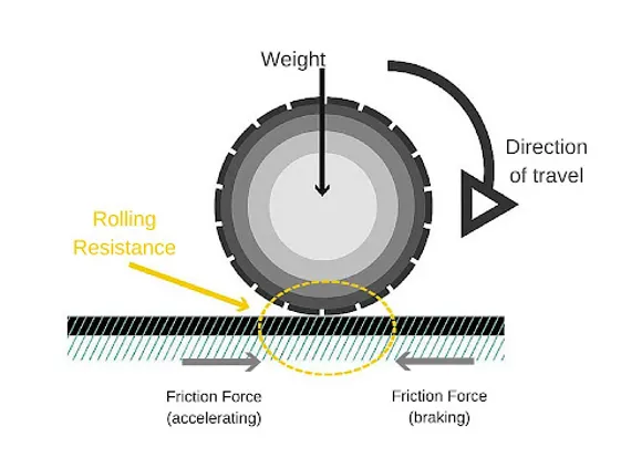
"Rolling Resistance"
- Rolling resistance is the energy that is lost when the tire is rolling. The main reason for the loss of energy is the constant deformation of the tire.
- Tire pressure, tire diameter, tire width, tire construction, tire tread and other factors all have an effect on rolling resistance.
- On a completely smooth surface the following applies: The higher the inflation pressure, the inferior the tire deformation and thus rolling resistance.
- Off road it is exactly the reverse: The lower the inflation pressure, the lower the rolling resistance. This applies equally on hard gravel roads and soft forest tracks. Explanation: A tire with low inflation pressure can adapt better to a rugged surface. It sinks into the ground less and the whole rotational mass is held back much less by the uneven surface.
- Tires with a smaller diameter have a higher rolling resistance with the same inflation pressure, because tire deformation is proportionally greater. The tire is flattened more and is “less round”.
- Wider tires roll better than narrower tires, with tires at the same pressure a narrower tire deflects more and so deforms more.
- Obviously, tire construction also has an effect on rolling resistance. By using less material, less material can be deformed. And the more flexible the material is, such as the rubber compound, the less energy is lost through deformation.
- Generally, smooth treads roll better than coarse treads. Tall lugs and wide gaps usually have a detrimental effect on rolling resistance.
-
The rolling resistance force (Frr) can be mentioned as
Frr = c * m * g
Where,
c = rolling resistance coefficient
m = mass of an object
g = gravity (constant 9.81m/s^2)
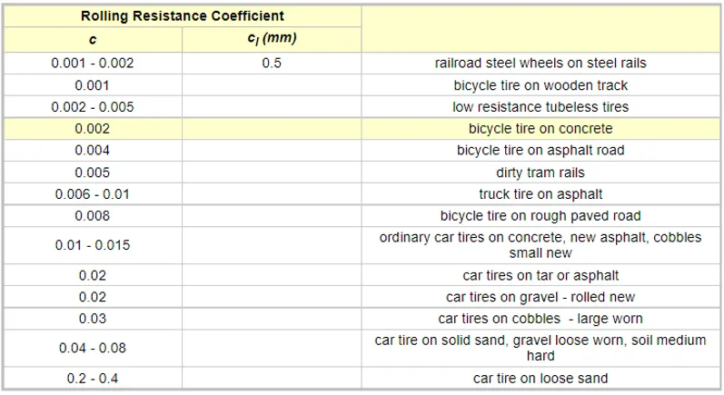
Some typical rolling resistance coefficients that can be used for different drive applications are given below
- Tire Pressure
-
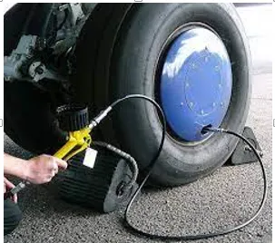
Actually, tires don’t support the weight of a vehicle. It is the air pressure inside the tire that supports the vehicle. The tire is basically a rubber container that holds the air the vehicle rides on. Setting the correct tire pressure is required for good handling, traction, and durability. Here is where the problem begins, we can’t just set it and forget it. Road conditions and temperatures play a significant role in the tire’s performance and safety. For every 10 degrees Fahrenheit change in ambient temperature, tire’s inflation pressure will change by about 1 psi. It will go down with lower temps, and up with higher temps. The typical difference between summer and winter temperatures is about 50 degrees F. – which results in a loss of about 5-psi and will sacrifice handling, traction, durability, and safety. How can we determine the proper tire pressure? Go by what the tire manufacturer recommends. The tire type, the load on the tire, and environmental conditions determine the proper tire pressure. As mentioned above the condition that is literally deadly is low tire pressure combined with a heavy load on the tire. The amount of weight you can support with a tire depends on the air in the tire. The more air in the tire the more weight the tire can support. The less air in the tire the less weight the tire can support. The max load is stamped on the side of the tire. The stamping will give a tire pressure number at a particular weight. As an example, “45 psi at 1450 Lbs”. The Tire Company is telling you that if we have 1450 Lbs on that tire, we must have 44 psi in the tire. We can measure the tire pressure with a tire pressure gauge.
Primarily 2 parameters play pivotal role in case of aircraft tires
-Deflation : The tires deflates in a controlled manner and consequently have direct impact on other systems
-Explosive brake up: This is a sudden outburst of tire in an uncontrolled way leading severe damage to secondary systems (may lead to crash landing)
-
"Brake Force"
- Braking the aircraft is quite an interesting, challenging but a rewarding experience especially during landing in rainy, storm or cross wind environment
- On top of using normal friction and hydraulics brakes, the aircraft are equipped with spoiler, reverse thrust technologies and parachute to land safely but still reducing the demand on regular friction/hydraulic brakes there by avoiding the skid and wear and wear and tire of tires
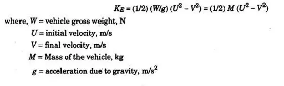
- Brakes force can be calculated using the following formula
PART - B
6. with the necessaary assumptions, calculate the force and power required to push / pull an aircraft by a towing vehicle
Considerations
To calculate the force and power required to push / pull an aircraft, following parameters to be calculated.
- Rolling Resistance Force : Frr
- Frictional force : Ff
- Drag Force: D
- Note: Since the push and pull of an aircraft happens on flat runways climbing force not considered
Assumptions
Coefficient of rolling resistance = 0.002
Coefficient of friction = 0.01
From the study table of different types of aircrafts and their weights, in this exercise weight range of 200kg to 3,00,000kgs is assumed. Mass of a towing vehicle is ignored (as the comparative weight b/w aircraft and towing vehicle is too big)
Key Note: Below calculation done considering the worst case aircraft weight of 3,00,000 kgs
Towing speed considered = 2m/s
Derivations
From this course, we gained insights on the following formulae
Frr = coefficient of rolling resistance * mass * gravity ------ (eq-1)
Ff = coefficient of friction * mass * gravity---------------------- (eq-2)
D = 0.5* drag coefficient*Area*(velocity)^2--------------------- (eq-3)
Pulling force / Tractive force = Frr + Ff + D ----------------------- (eq-4)
clc
clc

% Considerations

	% To calculate the force and power required to push / pull an aircraft, following parameters to be calculated.
	% Rolling Resistance Force : Frr
	% Frictional force : Ff
	% Drag Force: D
	% Note: Since the push and pull of an aircraft happens on flat runways climbing force not considered

% Assumptions

C = 0.002; % Coefficient of rolling resistance
f = 0.06; % Coefficient of friction
g = 9.81; % gravity constant
Cd = 0.08; % Drag Coefficient
m = linspace (200, 300000, 2000); % weight
a = linspace (50, 100, 2000); % area

%From the study table of different types of aircrafts and their weights, in this exercise weight range of 200kg to 3,00,000kgs is assumed

v = 2; % Towing speed considered

% Derivations From this course, we gained insights on the following formulae

% Total push / pull / tractive force : Rolling Resistance Force + Frictional force + Drag Force

Frr = C * m * g;

Ff = f * m * g;

D = 0.5* Cd *a * 1.2 * (v)^2;

Fpushpull = Frr + Ff + D;


plot (m , Fpushpull )
title ('push or pull force vs. aircraft weight')
xlabel ('aircraft weight (kg)')
ylabel ('push or pull force')

power = Fpushpull * v;

hold on

plot (m , power )
title ('push or pull power vs. aircraft weight')
xlabel ('aircraft weight (kg)')
ylabel ('push or pull power')
converting the above code to a simulink model
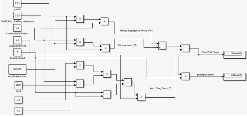
Result
7.
A) Design an electric powertrain with type of motor, it’s power rating, and energy requirement to fulfill aircraft towing application in Simulink. Estimate the duty cycle range to control the aircraft speed from zero to highest. Make all required assumptions. Prepare a table of assumed parameters. Draw a block diagram of powertrain.
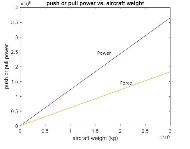
Step-1: From the previous question calculations the worst case force required is 182KN and power required is 363KW to pull/push an aircraft with weight of 3,00,000Kg
With the availability of this info, we shall now see the torque estimation. With the following assumption
T/M gear ration = G = 8
Efficiency = 0.7
Radius of the towing vehicle wheel = 0.3m
Torque is given by the following relation
T = (Fpushpull * radius of the towing vehicle wheel) / (Gear ratio*efficiency)
T = (1554KN *0.3) / (8*0.7)
T = 9.75K Nm
Hence, the torque required is 9.75K Nm to push / pull the aircraft
With this background we need to design an electric powertrain for the towing vehicle to enable the push back or pull an aircraft
The following selections are the key
Motor : considering energy needs, power rating & duty cycle
Battery as DC supply to power converter enabling AC power to the induction motor
Motor : We need a motor that can generate a power rating of 363KW
Considering the motor efficiency of 90% the input power required by the motor can be calculated as below
Efficiency = output power / input power
Input power = output power / efficiency = (363KW/0.90) = 403KW
Considering the calculated input power "MV Motors TM21-G" is chosen for this study, it has a rate voltage of 11KV and 209.1A rated current from its spec book
Power converter: Needed to convert the DC supply from battery to an AC for Induction motor operation
Input voltage is given by Vi = input power / rated current = 403KW/ 209.1 = 1.92KV
Hence, the inverter demands 1.92KV to generate power of 403KW
Duty Cycle : Determined by output power/input power = 0.899 (approximately 90%)
With this duty cycle the output voltage shall be = input voltage*duty cycle = 1.92KV*0.9 = 1.73KV
Battery Choice: To act as a DC energy source to power the vehicle. Battery choice is depending upon the amount of energy it can discharge and the rate of discharge
Energy is given by E = input power *time
We already have the input power. Now for time, lets us assume that the operation takes in 3min (or) 180sec
E = (403KW * 180sec)/3600 = 8.95KWh
Hence the choice of battery rating is 8.95KWh
Model of the system in simulink
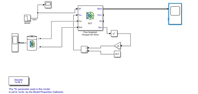
Input and Results
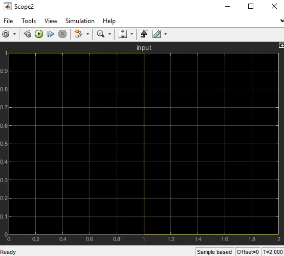
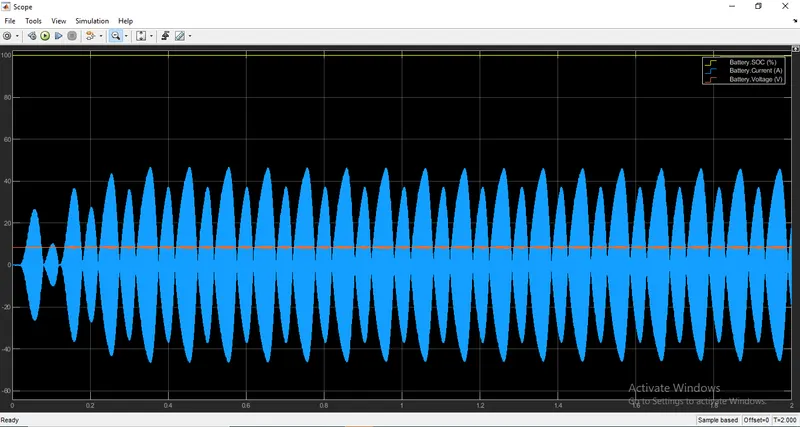
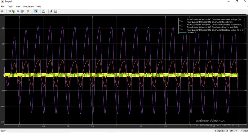
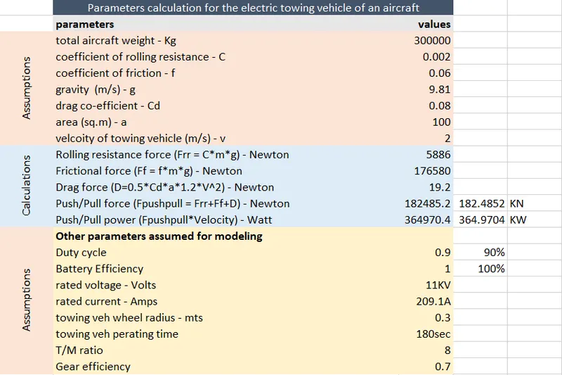
Table of assumed parameters
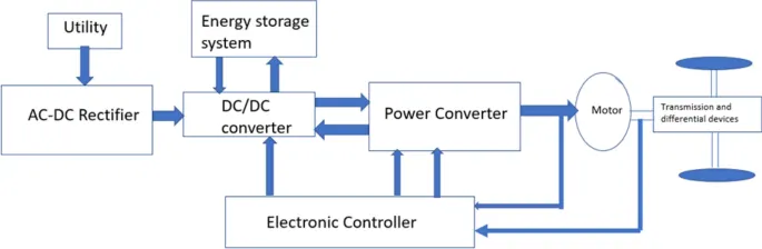
Electric block diagram
Flow of enegy from battery to wheels - > Forward Motoring
Flow of enegry from wheels to battery -> regenerative braking
Assumed Parameters and relevant values
B) Also, Design the parameters in excel sheet.
excel sheet created for parameters calculations and assumptions, (excel file is attached for your ref)