Week-7 Challenge: DC Motor Control
1.
A.Block diagram:
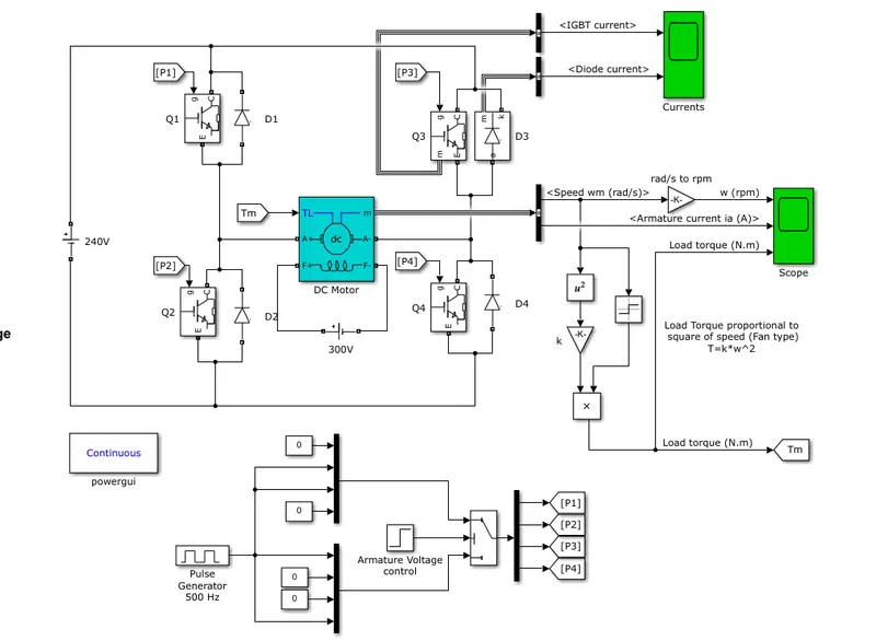
- Here the speed control of DC motor is done by using armature voltage control method where armature voltage is varied for speed control below the rated speed.
- Dc motor is placed between two legs of bidirectional switches which are realised by the pwer BJT in parallel with power diode. The field winding of motor is supplied by external source other than source used for motor making it a seperately excited DC motor. The whole arrangement represents a H shaped structure.
- The ouput port of 'm' of DC motor block is vector containing the measurement signals like Armature current (Ia), speed(w), field current(If), Electric torque(Te) out of these signals Ia and w are selected using the bus selector.
- Here the the load to DC motor is a fan type load where Torque is proportional to the speed of the fan T=k*w^2 so the w from bus selector is squared and then multiplied with proportionality constant.
- The torque obtained from speed is fed back to the input of DC motor block Tm.
Switching sequence:
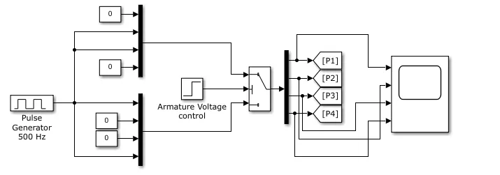
- A pulse generator of 500hz is used where the duty cylce is set.
- Two types of switching patterns are generated which are used to rotate fan in both the directions respectively.The lower switchinf pattern where the switching signal is given to switches Q1 and Q4 which when turned on the armture voltage is positive across the DC motor so motor rotates in positive direction while in upper switching pattern Q2 and Q3 are turned ON which when turned ON armature voltage is negative so fan rotates in negative direction.
- The choice between the two switching petterns is made by using a conditional switch where the second input(middle) is the control input where, if the condition for control input is satisfied the input passes through the input 1(top) if not satisfied passes through the input 2(bottom).
Opertion:
- The armature voltage control block is the control input to the conditional switch. The conditon is that when the control input is greater than 0.5 then the upper switcing pattern is given to the switches where the motor runs in negative direction and when less than 0.5 the lower switching pattern is given to the swirche where the motor runs in positive direction.
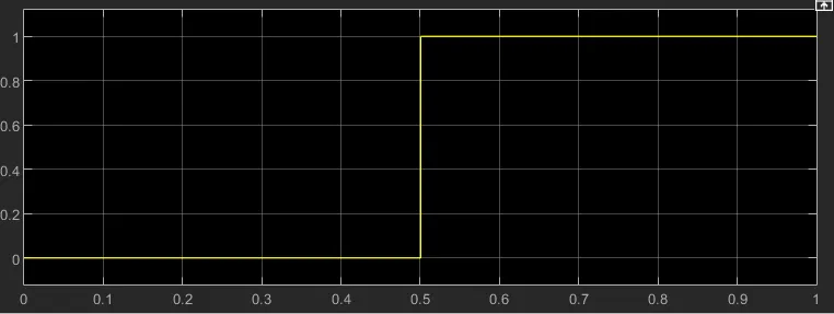
from above signal we can see for t<0.5 armature control voltage is less than 0.5 so motor runs in positive direction and at t>0.5 armature control voltage is greater than 0.5 so motor runs in negative direction.
results:
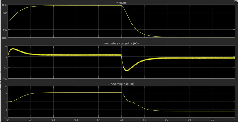
we can observe that at t<0.5 sec the speed in positive and as t is greater than 0.5 the the motor speed slowing decreaes and then becomes negative. There will be no instantaneous reversal in speed due to intertia.
Also there is change in current and torque direction. We can also say from the operation of motor that at t= 0.5 motor is transitioning from forward motoring to reverse motoring. In both the cases power is delivered to load from source to load s power is produc of torque and speed i.e., power is positive when both torque and speed both are of opposite sign, when they are of opposite sign then the power is negative which implies that power is delivered to source from the load.
B. The armature current expression for DC seperately excited motor is
`Ia=(Vt - Eg)/(Ra)`
Eg is directly proportional to speed, at starting the speed is 0 rpm so as the motor is turned ON at t=0 the speed is 0 rpm which implies that there will be no generated emf or back emf `Eg=>0`
`Ia=(Vt)/(Ra)`
so Ia will be higher at starting and as the speed picks up the back emf is generated and there will opposition created to the armature current. So thats why we observe shoot up at the starting. Similarly there will be shoot down when the motor is reversing its direction where similar condition for armature current arises.
C.
- Both the models can provide the 4 quadrant operation becauses both models form the H bridge where switches on both configurations are bidirectional.
- speed control usinf BJT h bridge is open loop control where duty cycle is given manually where as the DC7 drive is closed loop control where duty cycle is adjusted according to the Reference values given.
- PI controllers are used as speed and current controllers in DC7 drive. Speed controller output is current reference which is the input to the current controller, the output of current controller is compared with sawtooth signal to produce the PWM switching signal to the chopper switches. So the control signal generted is in accordance with the reference armature current. But in BJT H bridge drive the switching signals are generated using a pulse generated which are fixed untill the duty cylce is changed manually and ofcourse the swithinf frequency is constant in both the methods.
2. Two Quadrant Chopper:
- Two quadrant chopper is formed from the combination of class A(first quadrant) chopper and class B(second quadrant chopper).
- T1 and D1 correspond to class A and T2 and D2 correspond to class B.
- When T1 is ON output voltage Vo is positive and output current Io is positive, so chopper will work in first quadrant or forward motoring mode. As T1 is OFF Io freewheels through diode D1 where Io is still positive.T1 and T2 will be working in cpmplementary mode because if both switches are ON source is shorted through the switches resulting in short circuit current.
- When T1 is OFF T2 is turned ON which shorts the output voltage so Vo is 0v. When T2 is turned OFF, If the load is inductive then induced voltage drives the I0 in opposite direction ans travels to the source through the diode D2 entering into second quadrant or Forward Regenerative breaking.
results:

3. Brush Less DC (BLDC) motor:
construction:
Armature winding is in the stator which get the supply to represent an electro-magnet. Rotor is a permanent magnet, the interaction between the stator and rotor fluxes produce the torque.
- Armature winding is wound in 3phase manner just like an alternator.
- Rotor can also be placed outside the stator winding, this construction of BLDC motor is known as Out runner motor.
- BLDC motor also consist of rotor position sensors which produce electrical signals that indicate the current position of the rotor. Stator winding is driven form an electronic drive which is 3 phase inverter.
- Speed of BLDC can be controlled by controlling its stator voltage which can be achieved by controlling the DC input voltage of the inverter.
- To know which phase is needed to be energised frist and in what sequence the phases must be energised the HALL sensors are embedded in the rotor which senses the rotor position and is fed back to the controller. When Hall sensor comes in field of north pole of rotor logic 1 is generated and when south pole comes in vicinity logic 0 is generated.
Operation:
- When the stator coils are electrically switched by a supply source, it becomes electromagnet and starts producing the uniform field in the air gap. Though the source of supply is DC, switching makes to generate an AC voltage waveform with trapezoidal shape. Due to the force of interaction between electromagnet stator and permanent magnet rotor, the rotor continues to rotate.
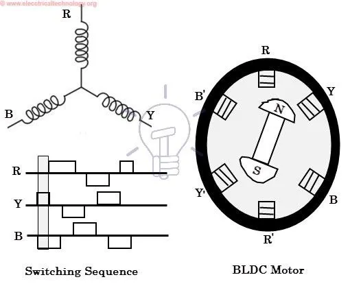
- Depending on the rotor position the hall sensor feed backs the rotor position to the controller, the controller decide which phase to excite first. Here in the above figure Y phase is energised first such that Y is S and Y' is N so the N of rotor is attracted by S of Y similary B phase is also excited at the same time where B is S and B' is N, so the N of rotor is attracted by the continously changing S of the stator rotating the rotor in clockwise direction.
- The direction of rotation is can be changed by giving the appropriate control signals to the phases.