Week-7 Challenge: DC Motor Control
1.Explain in a brief about operations of the BLDC motor.
EXPLANATION:
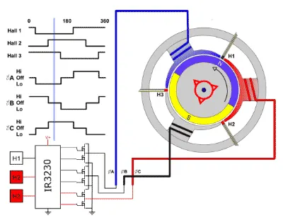
BLDC stands for Brushless dc motor as the name says the motor does not brush in them. It has a rotor that has a permanent magnet fixed and a stator has coil winding which is driven by three-phase supply. When the voltage is applied between the coils, the coil gets energized. As the coil gets energized the rotor and stator start rotating because of the magnetic field interactions of stator and rotor. It starts to rotate by the attraction and repulsion between the north and south poles. Like different poles get attracts and same poles get repulse. Due to attraction and repulsion, the motor starts rotating 180 degrees only in the three-phase supply. The BLDC motor has a hall sensor that is used to sense which coil is in an active state. Hall sensor is placed in airgap place. Hall sensor gives the shaft position feedback to the electronic controller unit. Based on this signal from a sensor, the controller decides the particular coils to energize. Hall effect sensors generate Low and High-level signals whenever rotor poles pass near to it. These signals determine the position of the shaft.
There are two types of rotor design i.e
- Outer Rotor design
- Inner rotor design
Outer Rotor design:
In outer Rotor design, the rotor surrounds the winding which is located in the core of the motor. The magnets in the rotor trap the heat of the motor inside do not allow it to dissipate from the motor. Such types of motor operate at low rated current and have low cogging torque.
Inner Rotor Design:
In the inner rotor design, the rotor is placed inside the stator, rotor magnets do not insulate heat inside and heat dissipation is easy. Thus the motor produces more torque.
Advantages of BLDC motor:
There is no sparking and much less noise during operation.
Bldc motors accelerate and decelerate easily as they are having low rotor inertia.
Due to the absence of brushes, the mechanical losses due to friction are less which enhanced efficiency.
Disadvantages:
cost is high.
The limited high power could be supplied to the motor are else, too much heat weakens the magnet and insulation of winding may get damaged.
2. Develop a 2-quadrant chopper using Simulink & explain the working of the same with the relevant results
EXPLANATION:
A chopper is known as a dc-dc converter which is a static device used for converting the variable dc voltage into a fixed dc voltage. They are two types:
- step-up chopper
- step-down chopper
step-up chopper :
If the output voltage is greater than the input voltage, then it is called a step-up chopper.
step-down chopper:
If the output voltage is less than the input voltage, then it is called a step-down chopper.
TWO QUADRANT CHOPPERS:
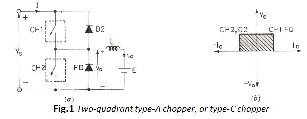
In this type of chopper, the average voltage will be always positive but the average load current might be positive or negative. The two switches ch1 and ch2 should not be turned simultaneously as the combined action cause a short circuit in supply lines.
When the current flows to ch1 to load, the inductor stores the energy. When ch1 is off, the freewheeling diode starts conducting and the output voltages vo is equal to vs. The direction of current gets reversed.
For the First quadrant, only ch1 and FD get conducting so the current flows from source-ch1-fd-load, as for the second quadrant only ch2 and d get conducting so the current flows to ch2-d-load. The Free-Wheeling diode action takes place at a time when both the MOSFET at off-state. so the inductor stored energy goes to load.
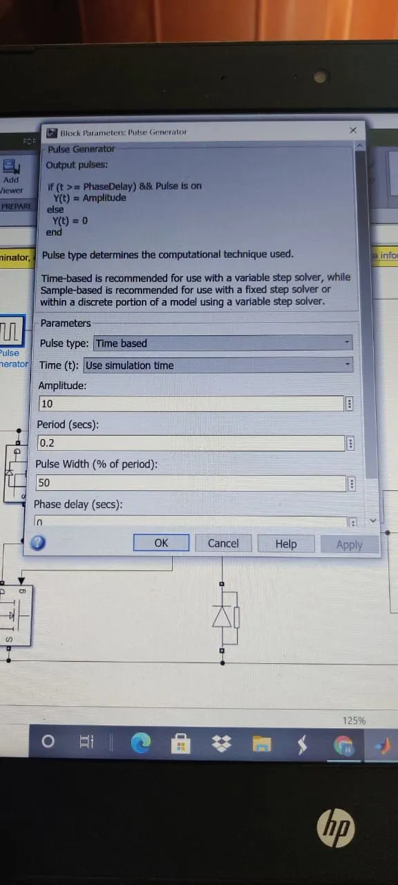
The value shown for the pulse generator is shown above:
OUTPUT OBTAINED FOR THE GIVEN VALUE IS:
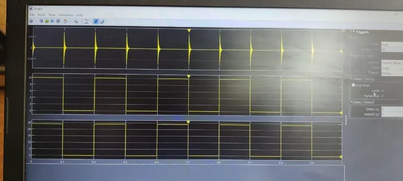
AS you see the limit didn't cross 10v and it get increase and decrease because of freewheeling action take place. As we set the duty period for 50% the curve drops up for 50 of its cycle time.
1. Explain a MATLAB demo model named ‘Speed control of a DC motor using BJT H-bridge’.
B. Comment on the armature current shoot-up from the scope results.
EXPLANATION:
The 200 HP DC motor is separately excited with a constant 150v DC field voltage source. The armature voltage is provided by an IGBT converter controlled by two pi regulators. The converters are fed by a 516 v DC bus obtained by rectification of 380 v Ac 50 Hz voltage source. In order to limit the DC bus voltage during dynamic braking mode, a braking chopper has been added between the diode rectifier and the DC7 block.
The first regulator is a speed regulator, followed by a current regulator. The speed regulator outputs the armature current reference used by the current controller in order to obtain the electromagnetic torque needed to reach the desired speed. The speed reference change rate follows acceleration and deceleration ramps in order to avoid sudden reference changes that cause armature over-current and destabilize the system.
The current regulators control the armature current by computing the appropriate duty ratios for four IGBT devices. In order to limit the amplitude of the current oscillations, a smoothing inductance is placed in series with the armature circuit.
The stability of the voltage and current supply is higher in the four-quadrant compared to BJT as the four-quadrant uses step by step ramping strategy.
Regenerative braking is possible in four quadrants but not in BJT.
It is widely used in the automobile sector for speed control of DC motors whereas BJT is used in robotics and electromechanical devices.
The current values are continuous in BJT whereas in four quadrants it is chopped
To change the direction of motors, current signals are interrupted in four-quadrant. whereas in BJT, the polarity of the current needs to be changed.
Comment on the armature current shoot-up from the scope results:
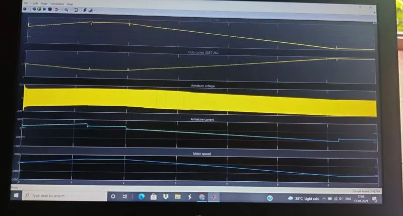
AS you note there are some spikes in the armature current waveform because at those times it gets decelerates due to the reversal of currents where the torque gets reduced after sometimes it reaches 0 the load torque reverses and becomes negative. The negative current now produces an accelerating electromagnetic torque to allow to follow the negative ramp.