Final Project: Design of an Electric Vehicle
The major components which are used in EV
- Drive cycle
- Driver
- H-bridge
- DC motor
- Battery Source
- Controlled PWM Voltage
- Vehicle and others
BLOCK DIAGRAM:
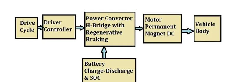
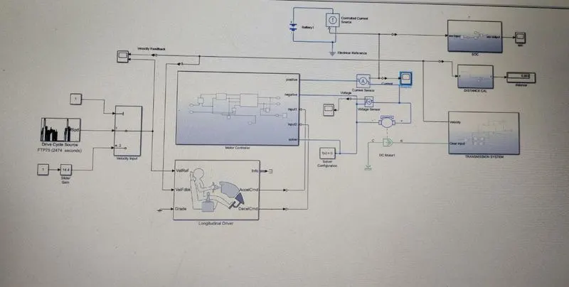
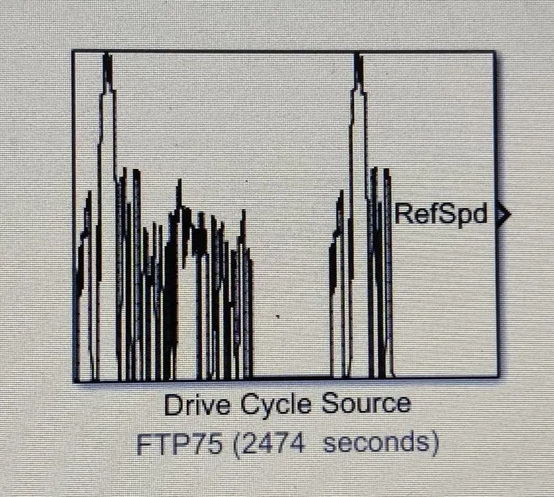
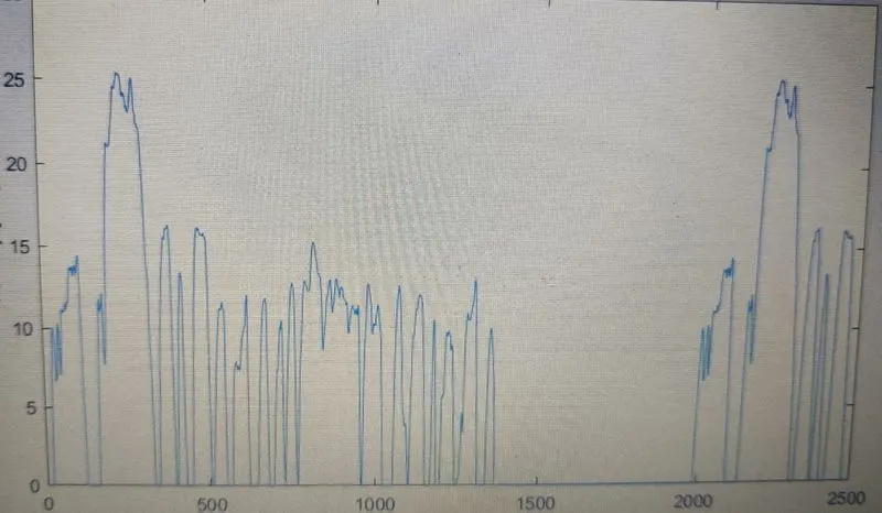
Starting with the Drive cycle, we have selected FTP75 drive cycle operation with test duration of 2474.
1. Drive Cycle:
2.DRIVER MODEL:
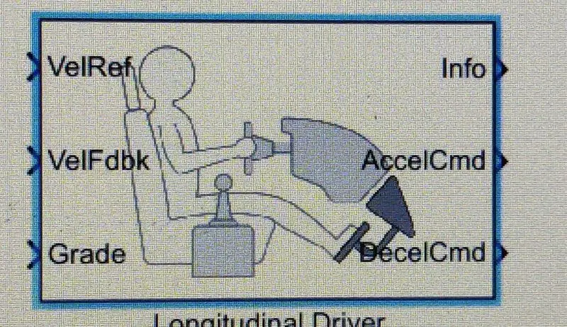
The Driver model has the input ports which are connected the following:
velocity reference--Drive cycle
Velocity Feedback---connected to vehicle body speed
Calculation act as closed-loop feedback to meet the desired speed as per reference input.
Grade=0
info= Not Connected
Acceleration command-connected to controlled PWM source through which itis is connected to controlled PWM voltage to vary duty cycle according to drivers input.
Deceleration command-connected to brake in H-bridge to maintain the speed according to the drive cycle and decelerate the vehicle.
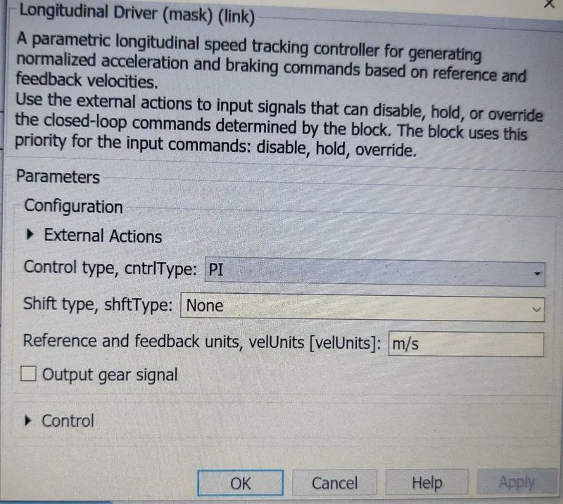
The PI control type is selected. This is nothing but the throttle pedal of the driver which will try to match with the input drive cycle given and according to PI controller will try to match whether acceleration or acceleration as per given input.
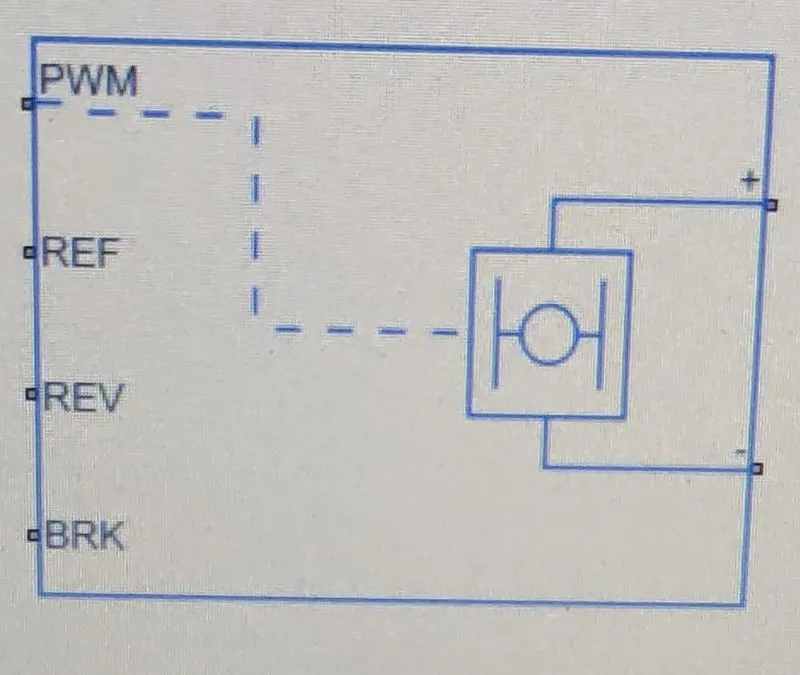
H-Bridge:
The H-Bridge helps in controlling the power that is input according to requirement. The output provided are converted voltage as per the controlled parameters.
The ports of input and output are PWM-pulse width modulation.
REF--controlling with reference
REV---controlling with reverse
BRK--controlling with brake and regenerative
+=controlled output to positive Terminal of the Motor
-=controlled output to Negative Terminal of motor.
The parameters selected in H-Bridge are:
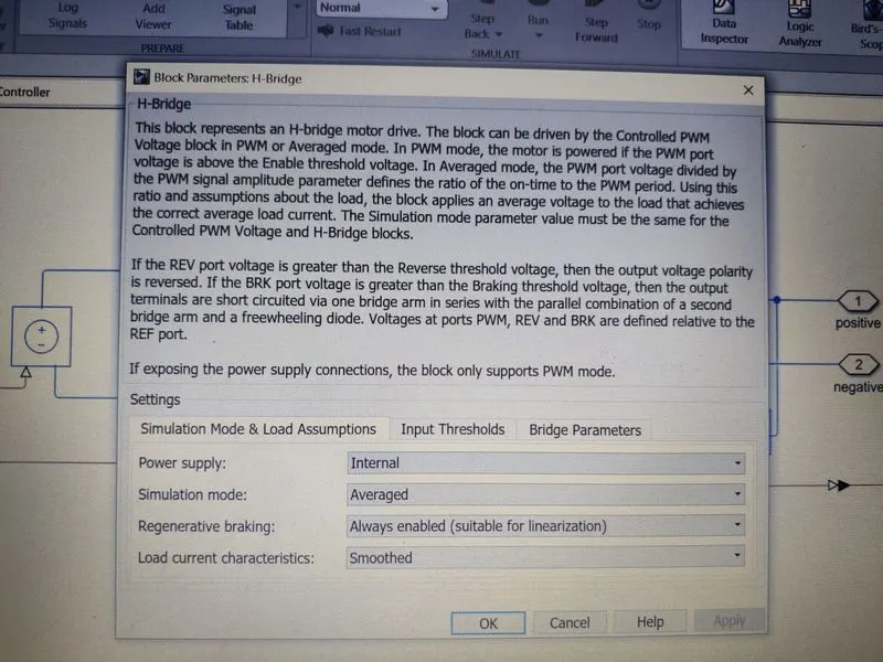
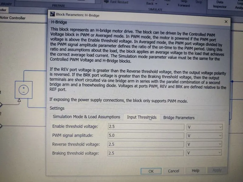
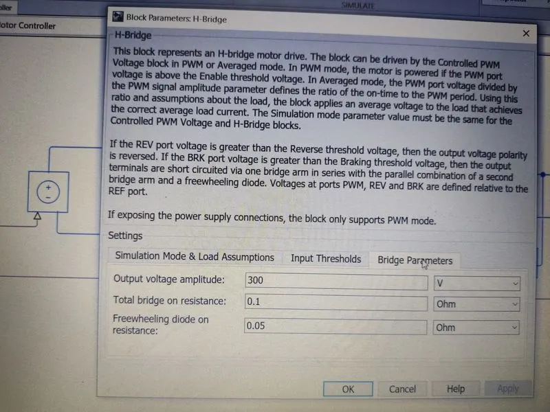
we have selected the internal type power supply and Enabled the Regenerative Braking for flow power back to battery while braking and decceleration to make EV efficient.
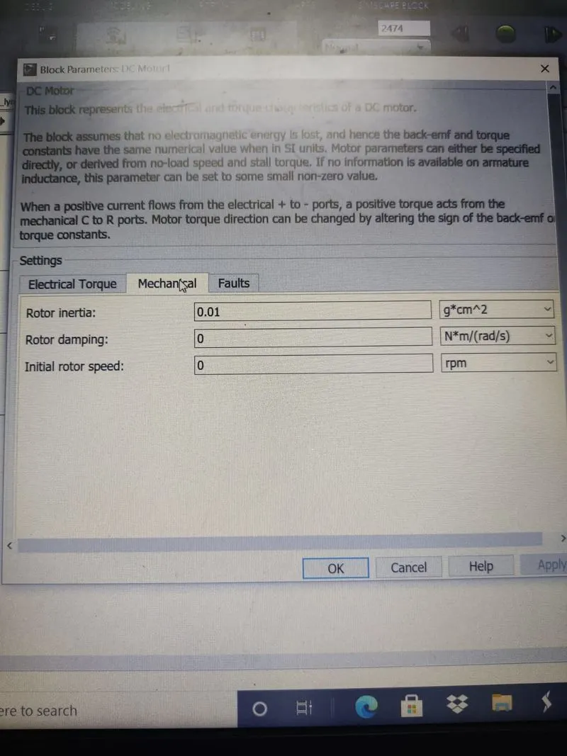
4. DC motor:
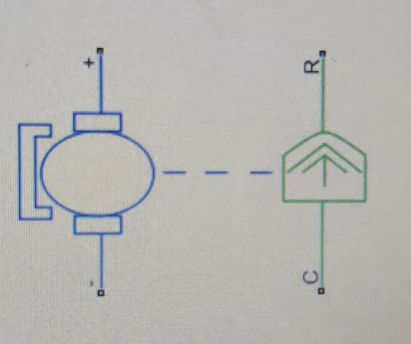
This is DC motor(Brushed motor) terminals are connected as mentioned below:
+=Electrical signal to the motor positive Terminals
-=Electrical signal to motor negative Terminals
C=connected to casing of motor connected with the mechanical rotational reference block
R=Rotor shaft of dc motor is connected to simple gear vary torque and speed.
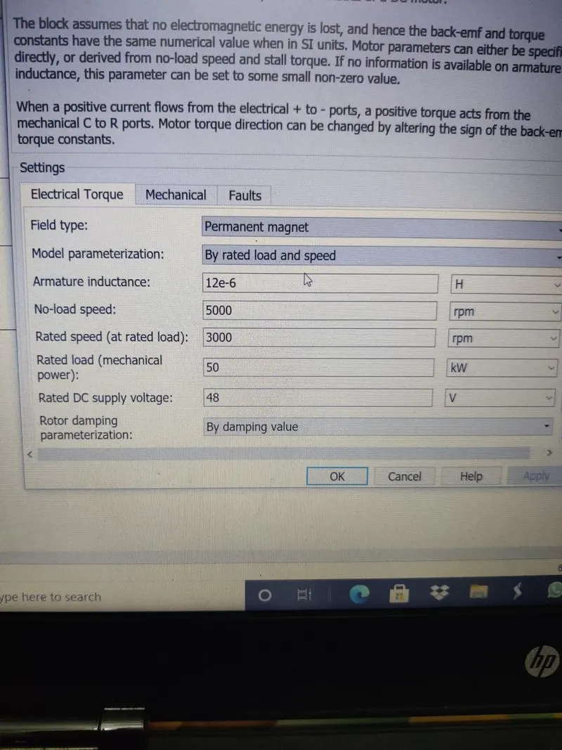
The parameters consider are:
5.Battery:
The battery is connected as a source to provide the voltage. The terminals are
+= represents positive terminals of operating sources
-+ represents negative terminals of operating sources
The battery is connected along with the SOC block to determine the state of charge of the battery. It helps to find how many hours we can run our vehicle.
The complete SOC block are:
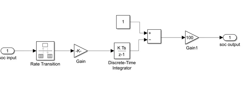
The block consist of a gain integrator that adds a block to determine the soc by integrating the velocity value. It is done by the coulomb counting method. The soc block is connected to the battery along with the controlled current block which counts the current values.
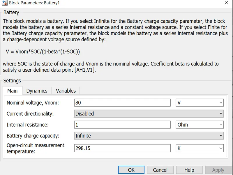
Nominals voltage is 80v, internal resistance is 1 ohm.
6. Controlled PWM Voltage:

controlled PWM Voltage to vary duty cycle according to drivers input. The controlled PWM voltage helps in keeping the modulated pulses as per required pulses. so that operation happens smoothly and higher variations are not observed.
ref+= Reference positive connected with the acceleration commands from the driver model
ref-= Reference negative connected with the deceleration commands from the driver model.
PWM=PWM connected directly to the H-Bridge
REF= it is directly connected to H-Bridge.
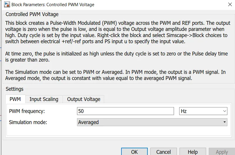
To have less simulation time we selected average instead of PWM simulation mode. PWM frequency is about 50 Hz. to make operation smooth and fast.
7. Vehicle:
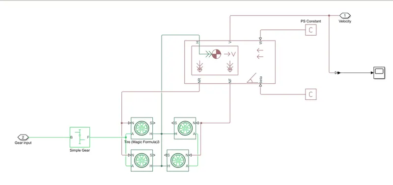
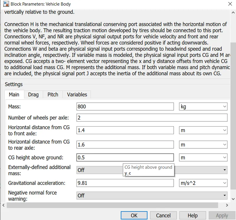
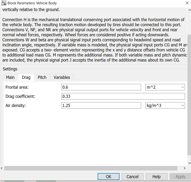
The components used are:
simple gear: For engaging the correct gear at the right duration where required.
Tyre-4 Tyre and the operation is All wheel drive.
a vehicle body- which contains weight other parameters of body
Angle-- The angle could be road condition the slope at which is car running.
Wind- The wind could be specified as per the condition where the vehicle has to driven.
The output obtained for our simulations are:
scope 1-- The velocity feedback and drive cycle source
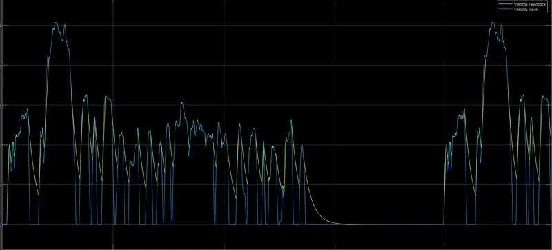
Here results of the drive cycle are shown. Here the velocity is following the input drive cycle. The maximum speed achieved is 20m/s. The motor mechanical power 50Kw at 48 V dc. The input drive chosen is FTP24. The vehicle speed output almost matches with reference speed input with small changes due to vehicle inertia and its control parameters.
The SOC Scope:
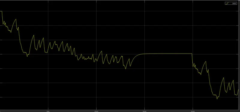
With the help of Above mentioned graph, the SOC graph drops to 88% from 100% at the time of deceleration and braking, the battery got recharged due to regenerative braking where the motor can act as generator and flow current to the battery.
Conclusion:
After various analyses carried out on the vehicle, we came to know that our velocity is tracking the input drive cycle and The battery SOC works fine by dropping from 100 to a certain point. The maximum speed achieved by our vehicle is 20m/s but it could not attain 25m/s because of DC limitations. If we select stator and rotor to supply voltage then magnetization power will be more and rotor will rotate with less current and voltage to match desired speed.