Final Project: Electric Rickshaw modelling
ABSTRACT:
In this project, we are going to build the MATLAB model of Rear Wheel Drive Electric Rickshaw by using permanent magnet brushed motors with a Lithium-ion battery. The main motto is to check" how the rickshaw performs for any three standard drive cycle inputs showing energy consumption, the temperature rise of motor and motor controller for vehicle cover around 100Km at a constant speed of 45 KMPH.
INTRODUCTION:
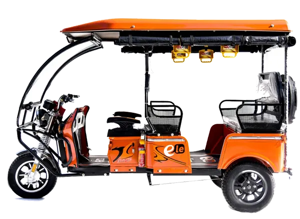
Electric rickshaws are three-wheel drivers powered by electric motors ranging from 600-1400 watts. They are mostly manufactured in India and China, only a few countries manufacture this vehicle. Battery run rickshaw could be low-emitter complimentary transport for the low-income people, who suffer most from a lack of transport facility if introduced in a systematic manner according to experts.
DESIGN AND CONSTRUCTION:
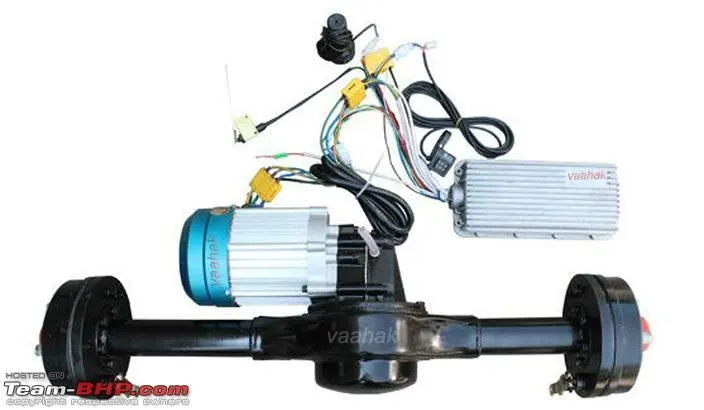
E-rickshaw has a mild steel tubular chassis, consisting of three wheels with a differential mechanism at the rear wheel. The motor is a brushless dc motor manufactured mostly in India and China. The electrical system used in the Indian version is 48 v and 60 v. Vehicles are made up of fiber also popular because of their strength and durability, resulting in low maintenance, especially in India. The body design is varied from load carriers, passenger vehicles with no. of roofs, to full body with windshields for drivers' comfort. It consists of the control unit. They are sold on basis of voltage supplied and current output, also the number of MOSFETs used. The batteries are mostly of lead-acid with a life cycle of 6-12 months.
 DRIVE TRAIN PARTS OF E-RICKSHAW:
VEHICLE BODY SIMULATION:
VEHICLE BODY:
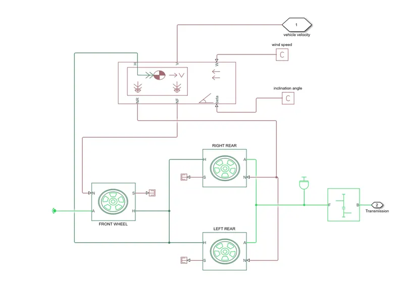
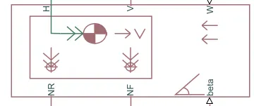
The motor will produce the rotational output which will give to the vehicle body and transmission system. The rotational output is taken by the gear system to maintain the constant speed throughout the transmission without any loss in speed from the motor to tires. The gear output is given to axles for rear tires, and the front tier is rotational-free because the system is Rear-wheel drive.
NF- Frontal normal wheel force
NR- Rear normal wheel force
V-output port of vehicle velocity
beta-input port of road inclination angle
W- input port of wind speed
H-Mechanical translational conserving port with the horizontal motion of vehicle body.
WHEEL(Tire-magic):
N- Physical signal input port that applies the normal force acting on the tire.
A- Mechanical rotational conserving port of wheel axle.
H- Mechanical translational conserving port for the wheel Hub.
S- physical signal output port that reports the tire slip.

SIMPLE GEAR:
B- base
F-Follower
connecting base and followed are mechanical rotational conserving ports. specify the relation between base and follower rotation directions with output shafts rotates. Output shafts rotate in the same direction as the input shaft. The base is connected to the motor shaft and F is connected to the rear-wheel drive.

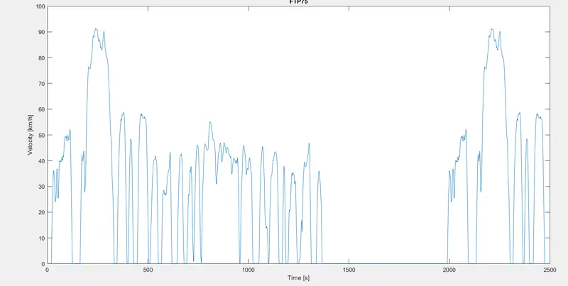
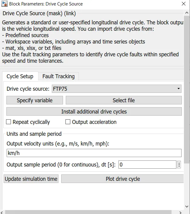
DRIVE CYCLE SOURCE FTP25:
Here Drive cycle is considered to be simulated on this model, where the drive cycle was simulated for 2427 seconds and the output graphs were plotted for the temperature of the DC motor and controller, SOC. The drive cycle here considered is the standard one given for reference purposes.
CONTROLLER:
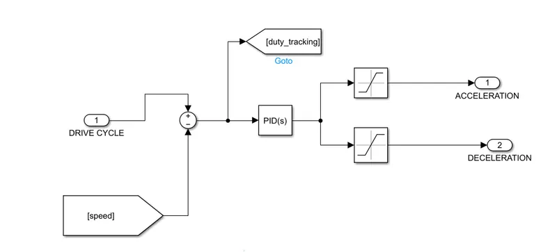
Here velocity of the vehicle is given as a feedback signal and reference is drive cycle data. Both the signal is given to the sum block where the result is given to the PID controller for desired acceleration and deceleration value. The controller should act according to the driver's function. Both the acceleration and deceleration command is given to the controlled PWM controller via the controller current source.
CONTROLLER PWM VOLTAGE:
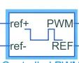
This block creates a pulse-width Modulated(PWM) voltage across the PWM and REF ports. The output is zero when voltage is low and is equal to output voltage amplitude when a pulse is high.
REF+: It is a positive electrical reference terminal connected with the controlled voltage source's positive terminal which received the drive cycle input from the acceleration command of the PID controller.
ref-: Negative terminal, connected to the electrical reference (ground) and negative terminal of the controlled voltage source.
PWM: Pulse width modulated signal, an electrical reference signal port connected to PWM port of H-BRIDGE.
REF: Floating zero reference connected to REF and REV ports of H-Bridge.
H-BRIDGE:
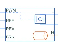
PWM: pulse width modulus signal where generated PWM voltage signal is given to H-bridge to control the motor
REF: This is the reference port which is an electric conversing port associated with floating zero volts.
REV: Reverse port.
BRK: Brake port.
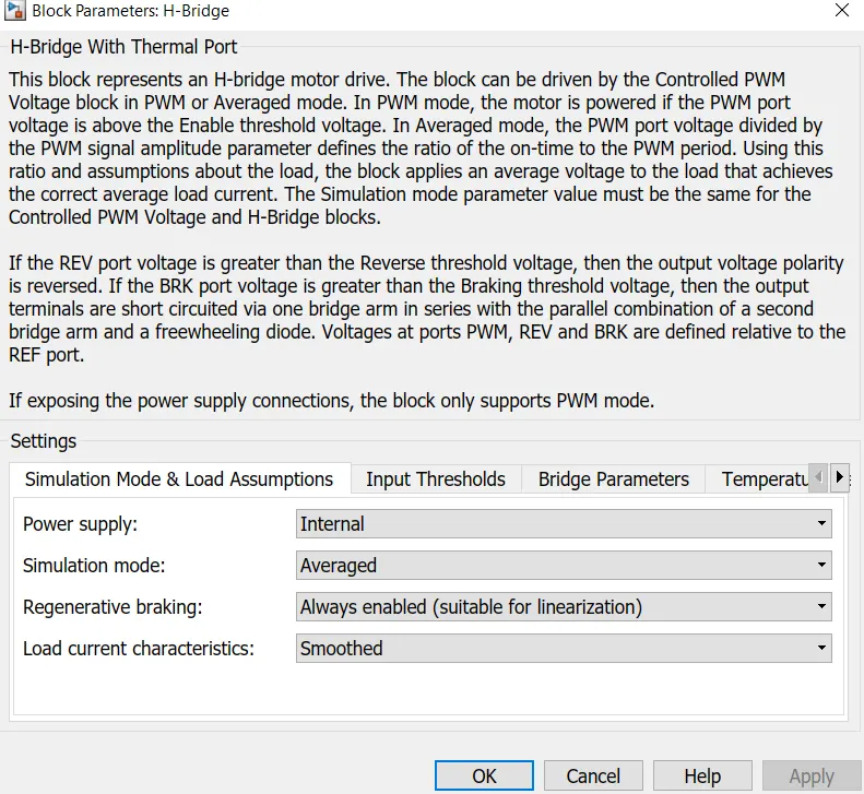
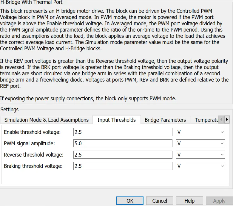
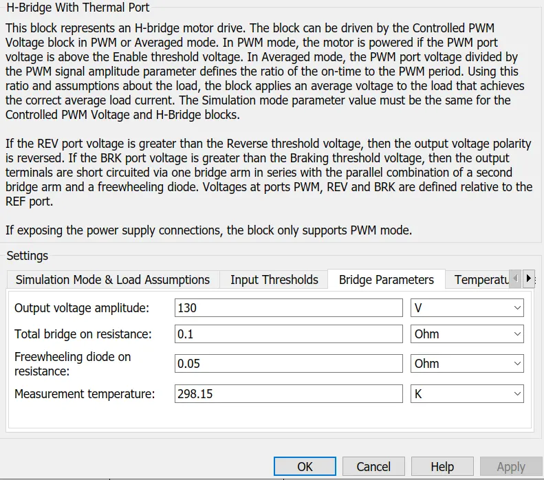
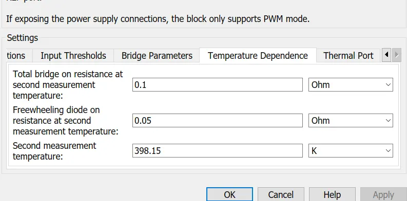
In this block, the PWM port is connected to the PWM port of the controlled PWM voltage block, REF and REV are connected to the REF block of the controlled PWM voltage block. The BRK port is connected to another controlled voltage source that has input from the deceleration command. The positive terminal of the H-bridge is connected to the positive port of the current sensor and further connected to the positive terminal of the DC motor via the negative terminal of the current sensor and the negative terminal of the DC motor.
H: Temperature sensor port where temperature sensor was connected with the thermal reference block.
CONTROLLER CURRENT SOURCE:
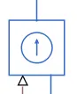
This block represents the ideal voltage source that is powerful enough to maintain the specified voltage at its output regardless of the current passing through it. This block has one physical signal input port and two electrical ports associated with its electrical terminals.
Two of these blocks were used in this subsystem one for acceleration and the other for deceleration.
TEMPERATURE SENSOR:
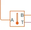
This block measure temperature in the thermal network. There is no heat flow through the sensor. The physical signal port T reports the temperature difference across the sensor. The measurement is positive when the temperature at port A is greater than the temperature at port B else negative.
THERMAL REFERENCE:
This block represents a reference point in the thermal network where the temperature is equal to absolute zero.
ELECTRICAL AND MECHANICAL REFERENCE:
Both the block used for grounding purposes.
CURRENT SENSOR:
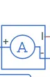
This block represents the ideal current sensor. A device that converts current measured in any electrical branch into a physical signal proportional to current. Connections + and - are conserving electrical ports through which a sensor is inserted into the circuit. Connections I is a physical port that outputs the current value. The current sensor is connected series with H-Bridge where positive to positive and negative to DC motor.
SOLVER CONFIGURATION:
This block is needed to start the simulation and is used to solve the Simulink model. This block can be connected anywhere in the system.

INERTIA:
This block represents an ideal mechanical rotational inertia. The block has one mechanical rotational conserving port. The block positive direction is from its part to the reference port. This means that the inertia torque is positive if the inertia is accelerated in the positive direction.

STATE OF CHARGE(SOC):
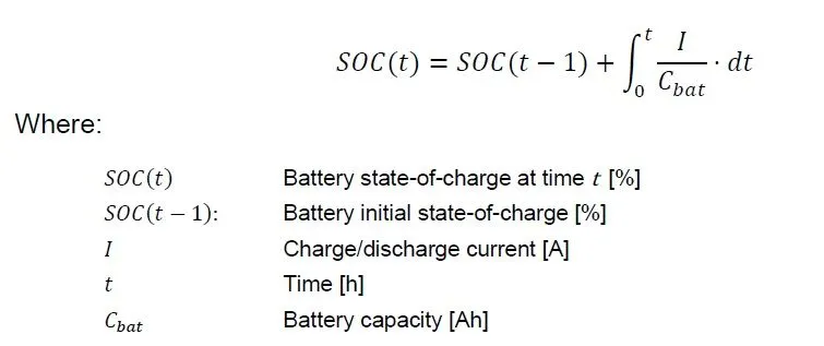
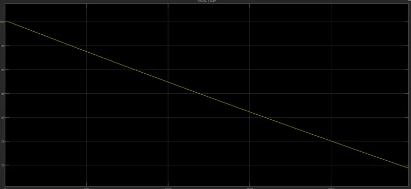
State of charge is the level of charge of an electric battery relative to its capacity. The units of SOC are percentage points i.e 0 means empty 100% is the battery is fully charged. It is normally used when discussing the current state of the battery is used while depth of discharge is most often seen when discussing the lifetime of the battery after repeated use.
CONTROLLED CURRENT SOURCE:
It is used where the generated current signal is given input from the lithium-ion battery to the motor block.

SOURCE TYPE =DC
POWER GUI:
The power GUI block allows you to choose one of these methods to solve your circuit.
- continuous which uses a variable-step solver from Simulink.
BATTERY SUBSYSTEM:
BUS SELECTOR:
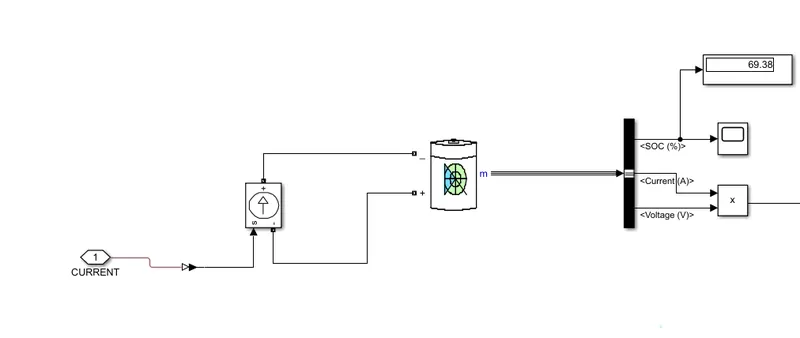
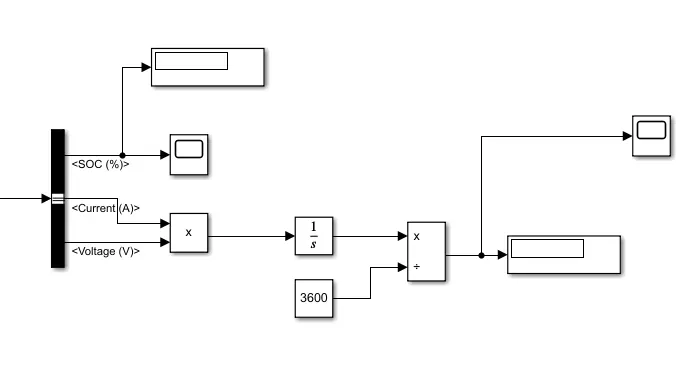
This block accepts a bus as an input signal which can be the creator. The bus selector shows the list of the parameter that needs to be shown. Here I have chosen the soc, current, voltage parameters to show.
MOTOR AND ITS CONTROLLER BLOCKS:
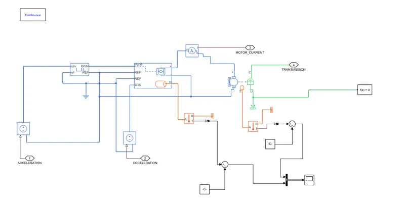
In this block, the generated acceleration and deceleration command from the PID controller is fed to control PWM voltage and H-Bridge to control the motor according to driver requirement. The thermal port is enabled to identify how much heat the motor and controller are generating which is sensed by the temperature sensor. The motor is supplied by the Li-ion battery pack of 48 V and 75 AH. The generated current is fed to the Li-ion battery via a controlled current source.
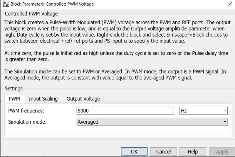
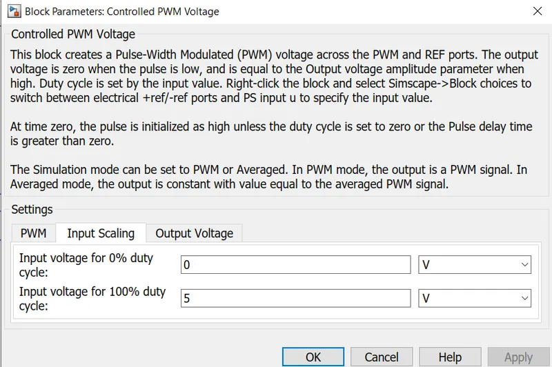
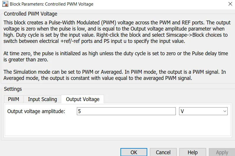
THE PARAMETERS FOR H-BRIDGE:
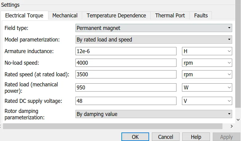
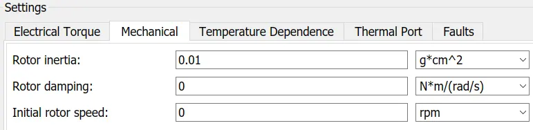
DC MOTOR PARAMETERS:

Energy Consumed:
By integrating the power with time, we get energy. So with the product block, we multiply the generated current and voltage value and then integrate with a time limit of 0 to 3600.
DISTANCE:
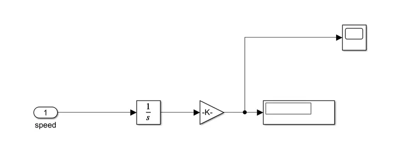
The output port of the vehicle body subsystem is connected to the integrator which basically gives the velocity of the vehicle. The velocity is divided by 1000 which gives the distance traveled by a vehicle.
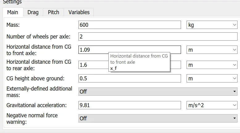
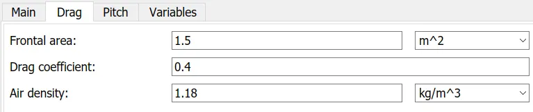
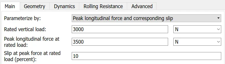
THE PARAMETER IN VEHICLE BODY:
RESULTS AND CONCLUSIONS:
After running the simulation for 2427 seconds, the results we obtain are
SOC drops from 100-68
Energy consumed for 2427 seconds by the battery is 1200
The distance traveled by the vehicle for 2427 seconds is 7.67 km.
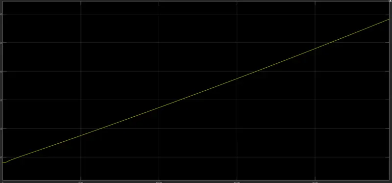
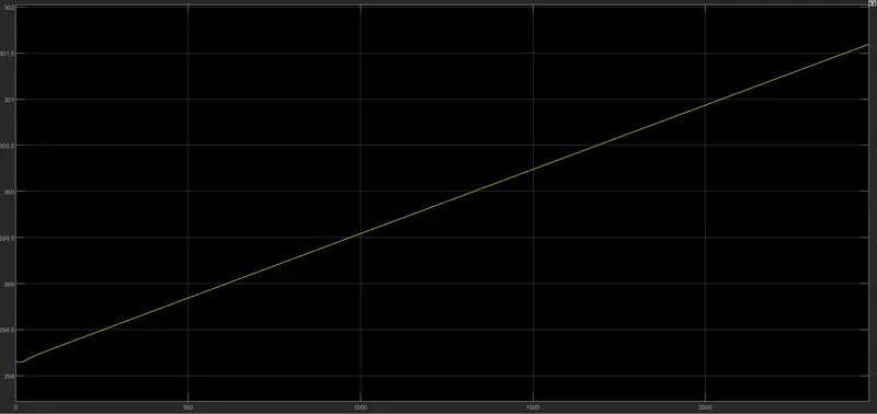
The temperature of the motor and controller are 347 and 306 kelvin
SOC GRAPH:
TEMPERATURE GRAPHS:
ENERGY CONSUMED GRAPH: