Week-7 Challenge: DC Motor Control
1.A)Speed control of DC motor with BJT H-bridge:
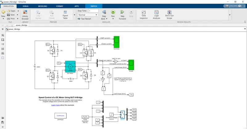
The above diagram shows the demo model of a dc motor with BJT H-bridge.
The input to the circuit is given by pulse generator.In the pulse generator block we can give the amplitude and the duty cycle of necessary value.
Then a switch block is connected to the pulse generator through a armature voltage controll block.
The switch block splits the power into four type namely p1 p2 p3 p4. into a goto block.The power from the goto block are taken out from a from block which goes into the control signals of the bjt of Q1,Q2,Q3,Q4.These signals are used to turn on and off the bjt.
The H-bridge consists of 4 bjt and 4 diodes.
1.Q1 and Q4 are turned on for forward motoring operation.When Q1 Q4 aare on the motor receives a positive current and conduction takes place.D1 and D3 are freewheeles when Q1 Q4 are turned off so the conduction remains continuous.
2.Q2 and Q3 are turned on for reverse motoring operation.When Q2 Q3 are turned on the motor receives a negative curent and conduction takes place in reverse direction.D2 and D4 are freewheeled when Q2,Q3 are turned off so the conduction remains conduction.
The H-bridge has the coneections of transistors for full control of the circuit for a dc supply.
The mechanical input to the motor is given by the Torque
T=K`omega^2`
The torque also given by a got and from block using the speed value generated by the motor as a output.
Some constants and gain blocks are used for the conversion of speed value in rad/s to rpm.A bus sector is used to connect the rpm,armature current value to the scope.Simillarly diode current and the bjt current is also senn through a scope.
B)Armature current shoot-up:
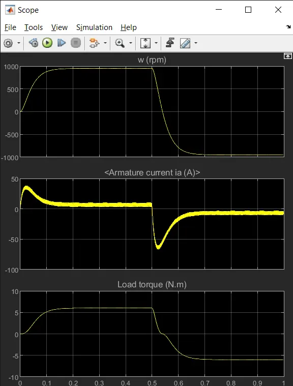
The scope result of the above model will give as the result as shown above.The armature current is obtained from the operation of the dc motor and the torque is produced as the square of speed.
It is seen that there is sudden raise in the current value during the start of motor when the speed of the motor is also increasing.
After the sudden raise the current value tend to remain in constant valuse as so the speed value.
After a duration of 0.5 sec as set in the pulse generator the speed value drops as a result the armature curent see a suuden shhot up in the negative terminal.
The shoot up range of the armature current can be controlled by varying the duty cycle and the duration i the pulse generator block.
C)Four quadrant operation vs Two quadrant operation:
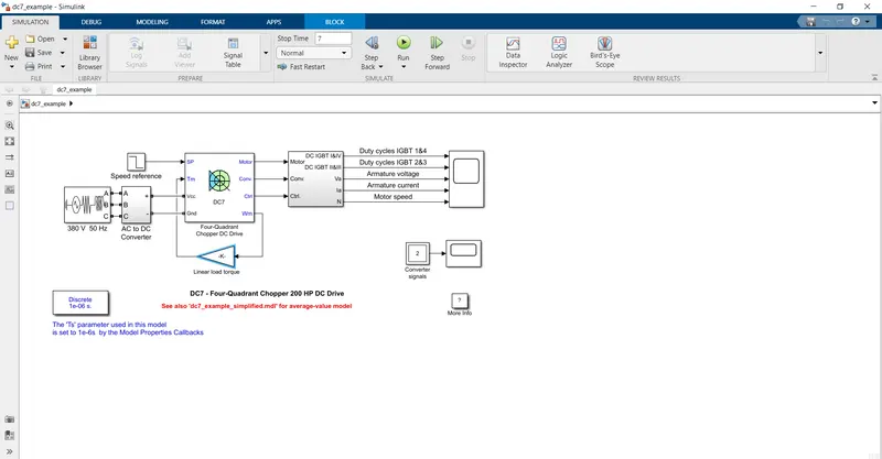
The above model shows the 4 quadrant control of a dc motor with igbt converter controlled by 2 PI controller.For proper operation of the motor the the igbt 1,4 are opposite to that of igbt 2,3.
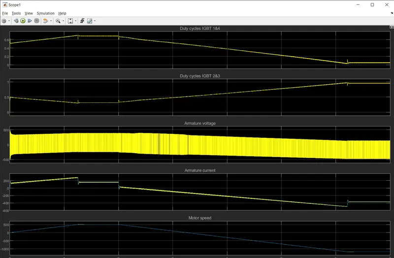
The above scope is the result of the 4 quadrant operation of the dc motor.
Comparison of H-bridge and 4 quadrant operation:
1.In H bridge motor can operate only in two region namely forward motoring and reverse motoring.In 4 quadrant operation it can operate in four region namely forwardmotoing, reverse motoring,forward braking and reverse braking.
2.The speed referance can be fed to 4 quardrant operation whereas it cannot be done in H-bridge.
3.The current supplied to each source in the H bridge remains same whereas that in the 4 quardrant the current is not same.
4.The control of speed is done effictively in 4 quadrant operation than the H-bridge operation.
5.In Ev ,H-bridge is used in the charging of the vechicle as the advancement of modern technollogy whereas the 4 quadratant is used in industries and other commercial use.
2.Two quadrant chopper:
Two quadrant chopper is known as type c chopper.
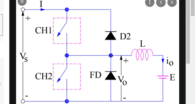
When chopper CH1 is switched ON, source Vs directly gets connected to the load and hence, load voltage Vo is equal to source voltage. The direction of load current is from source to load as shown in the circuit diagram which is assumed positive.
When chopper CH2 is switched ON, load DC source E drives current through CH2 and load. The direction of this current io will be opposite to that shown in circuit diagram and hence is assumed negative.
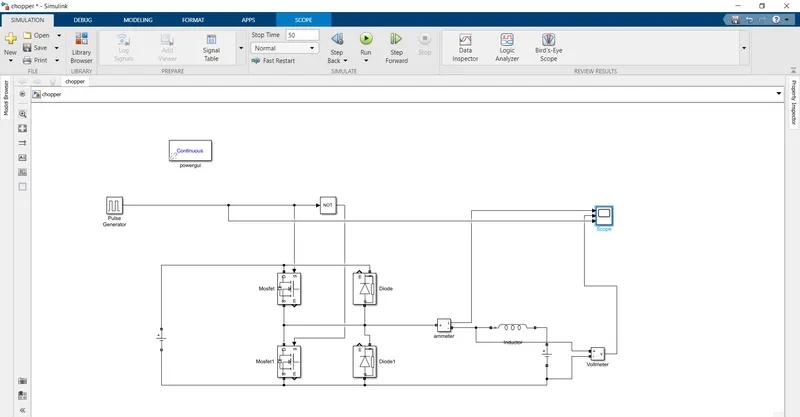
The type c chopper is modeled in the above model.Mosfet is connected as the switch in the model and the diodes are connected parallel to it.
Pulse generator is given as the input to the mosfet gate terminal.The pulse genarator is connected with not gate and the output is given to the another mosfet.
The amplitude of the pulse generator is set as 1 and theduty cycle is set as 50%.So we get half duration of on cycle and half period of of cycle.
During first cycle mosfet will turned on and mosfet1 will be turned offthe voltage is measured across the inductance through a scope.
During second cycle mosfet1 will be turned on and the mosfet will turned off and current is also measured at the end of inductor through the scope.
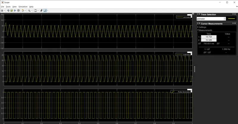
The output obtained is shown in the above diagram.The curent from the chopper is raised during the on period of the pulse generator and decreased during the period of off period of the pulse generator.
The voltage also raised to a peak value and decreased and reduced to zero as the operation of the chopper.
3.Operation of BLDC motor:
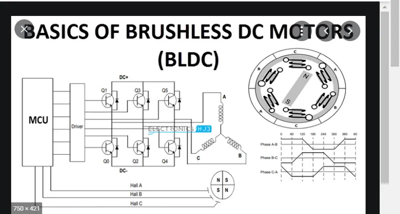
In this motor, the permanent magnets attach to the rotor. The current-carrying conductors or armature windings are located on the stator. They use electrical commutation to convert electrical energy into mechanical energy.
The main design difference between a brushed and brushless motors is the replacement of mechanical commutator with an electric switch circuit. A BLDC Motor is a type of synchronous motor in the sense that the magnetic field generated by the stator and the rotor revolve at the same frequency.
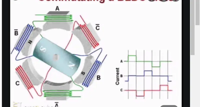
BLDC motor works on the principle similar to that of a brused dc motor. The Lorentz force law which states that whenever a current carrying conductor placed in a magnetic field it experiences a force. As a consequence of reaction force, the magnet will experience an equal and opposite force. In the BLDC motor, the current carrying conductor is stationary and the permanent magnet is moving.
When the stator coils get a supply from source, it becomes electromagnet and starts producing the uniform field in the air gap. Though the source of supply is DC, switching makes to generate an AC voltage waveform with trapezoidal shape. Due to the force of interaction between electromagnet stator and permanent magnet rotor, the rotor continues to rotate.
With the switching of windings as High and Low signals, corresponding winding energized as North and South poles. The permanent magnet rotor with North and South poles align with stator poles which causes the motor to rotate.
Advantage:
- Less overall maintenance due to absence of brushes
- Reduced size with far superior thermal characteristics
- Higher speed range and lower electric noise generation.
- It has no mechanical commutator and associated problems
- High efficiency and high output power to size ratio due to the use of permanent magnet rotor
- High speed of operation even in loaded and unloaded conditions due to the absence of brushes that limits the speed
- Smaller motor geometry and lighter in weight than both brushed type DC and induction AC motors.