Week-7 Challenge: DC Motor Control
1. A. Explain a MATLAB demo model named ‘Speed control of a DC motor using BJT H-bridge’.
Indroduction:
- In this MATLAB demo model named speed control of a DC motor using BJT H- bridge retifier. BJT is using for switching operation similar to the operation of IGBT.
- When BJT conducting a forward voltage Vf is developed between collector and emitter similar to the IGBT conduction time.
- Therefore in this MATLAB circuit model insted of using BJT here they using IGBT block.
- This IGBT block does not triggers gate current (or) gate pulse by itself.
- Here we controlling the IGBTs with the pulse generator block based on pulse generator duty cycle ratio that much amount of voltage only feed to motor.
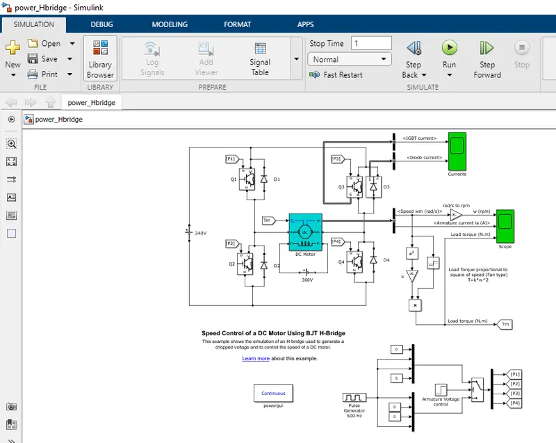
- Here below I have shown BJT H- bridge retifier simulink model overview.
1. Pulse Generator:
Pulse generator is used to generate gate pulse to the IGBTs to turn ON and OFF.
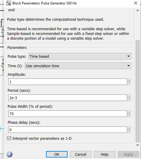
Pulse generator block parameters are
Ampletude=1
Pulse widh= 75%
Phase delay=0
Time period=2e-3 (or) 0.002
Here total time period of during ON to OFF (or) 1 to 0 is T=0.002
W.K.T f=1/T
f=1/0.002=> f=500Hz
In electrical and electronics duty cycle is reperesented as percentage of phase duration (or) Pulse wide. Here the percentage of pulse duration 75 % therefore duty cycle d=75%.
W.K.T the average output voltage of Power electronic swich Vo=Vbat*d
Here the applied battery voltage is Vbat= 240V
So the input voltage given to the motor through IGBT switch is 180V.
The armature mean voltage can be varied from 0 to 75%. Here in pulse generator duty cycle is specified as 75%.
2. DC Motor:
Here we using preset DC motor model(5HP 24V 1750rpm)
It simulate a fan type of load.
3. Motor load torque:
Here the motor load torque is calculated by output signals of motor speed(ω) and armature current(Ia).
In DC motor load torque is directly propotional to squares of speed.
T=kω^2 N.m
Where k = motor design constant
Here its value is 6.062e-2
4. Signum Block:
- Signum block for positive inputs it gives +1 output, for negative inputs it gives -1 output ad for 0 input it gives 0 output.
- Why we are using this block means if the motor speed is in negative direction (or) reverse direction this block will sense and reflect in motor load torque calculation.
5.Switch Block,GoTo blcok,From block & Demux:
- Below the bridge circuit a switch block and demultiplex block. The outpur signal from the switch block is fed to demux this will split the single input pulse signal into four output signals and each signals are send to GoTo blocks named as P1,P2,P3&P4.
- This GoTo block signals are given as input for Q1,Q2,Q3&Q4 by using the From block.
6. Step signal block.
- Here the step signal block is used as a armature voltage control.
- In this the armature voltage step time is specified as 0.5 sec.
Operation of H-bridge circuit:
- This H-bridge circuit consist of four IGBTs with Diode pairs.
- At a time two IGBTs are turned ON simultaneously.
- Here each IGBTs are named as Q1,Q2,Q3&Q4 and each Diodes are named as D1,D2,D3&D4.
- Q1 & Q4 are fired/triggered/pulse applied to turn ON the IGBTs during positive voltage is applied to the motor armature winding and the load current Il flow from higher potential to lower potential through the path Vs-Q1-M-Q4-Vs
- When Q1 & Q4 turned OFF the diodes D3 & D2 comes in action and act as free wheeling diode.
- When the supply voltage is absent due to this the energy stored in armature winding is free wheel through D3 & D2.
- The energy stored in motor winding dessipates its load current Il flow from higher potential to lower potential through the path M-D3-Vs-D2-M.
- Q2 & Q3 are fired/triggered/pulse applied to turn ON the IGBTs during negative voltage is applied to the motor armature winding and the load current Il flow from higher potential to lower potential through the path Vs-Q2-M-Q3-Vs
- When Q2 & Q3 turned OFF the diodes D1 & D4 comes in action and act as free wheeling diode.
- When the supply voltage is absent due to this the energy stored in armature winding is free wheel through D1 & D4.
- The energy stored in motor winding dessipates its load current Il flow from higher potential to lower potential through the path M-D1-Vs-D4-M.
Q1 & Q4 operated as forward motoring: Because here speed and torque both are positive so power devloped is also positive.
Q2 & Q3 operated as reverse motoring: Because here speed and torque both are in reverse direction or in negaive values but the devloped is positive direction.
Output results:
- The scope output named as current shows the IGBT (Q3) & diode (D3) current outputs during the duration of duty cycle.
- From the above graph it shows that when intial 0.5sec the diode D3 is in ON condition and IGBT Q3 is in OFF condition at this time current flowing through diode D3.
- The pulse generator gives pulse signal to IGBTs according to step time specified in armature voltage control block. Here step time is specified as 0.5sec.
- After 0.5sec of step time pulse generator gives pulse signal to IGBT Q3 now diode D3 gets turn OFF andQ3 gets turn ON at this time current is flowing through Q3.
B. Comment on the armature current shoot-up from the scope results.
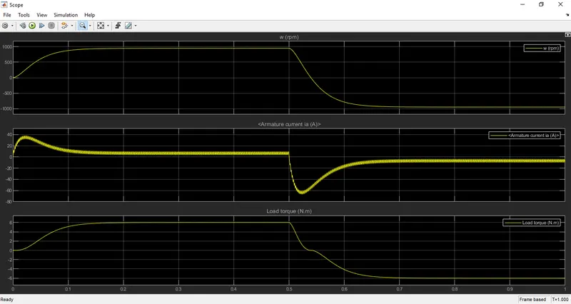
- From the above graph we can observe at the initial starting time of DC motor there is sudden shoot up in armature current.
- (0.50):Sudden shoot up in armature current Ia is because of while applying positive voltage to motor. Q1 & Q4 turned ON by pulse generator at this time the current is allowed to fed to armature winding of motor. So at starting time of motor its armature current gets shoot up at the same time we can observe speed get increases for certain period of time.
- At this time period motor voltage and current both are in positive direction so the motor rotating in forward direction.
- (10.5):After 0.5sec time period negative voltage is applied pulse generator armature voltage controler turn OFF Q1 & Q4 and turn ON Q2 & Q3.
- During this time period armature current Ia shoot up in reverse direction.
- At this time period motor voltage and current both are in negative direction so the motor rotating in reverse direction.
By reducing the pulse width in pulse generator we can reduce the shoot up armature current.
C. Refer to the help section of ‘The Four-Quadrant Chopper DC Drive (DC7) block’. Compare it with the H-bridge model.
Introduction:
Before get into the four quadrant DC drive (DC7) block. We need to know what is chopper, four quadrant operation of motor and four quadran chopper circuit operation.
First what is chopper?
- Chopper is a static device that converts fixed DC to Variable DC it is also called as DC-DC converter.
- There are two types of chopper they are I.) Step up chopper II.) Step down chopper.
I.) Step up chopper: Output voltage is more then the Input voltage.
II.) Step down chopper: Output voltage is less then the Input voltage.
Four quadrant operation of motor:
- A motor operated in all the four quadrants is called four quadrant DC drive.
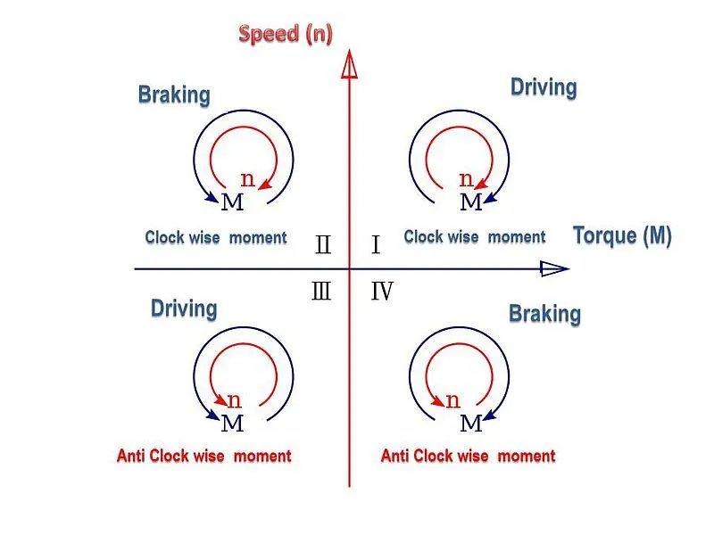
- The operating modes of motor in four quadrants are:
- Forward Motoring (Quadrant-I)
- Forward Braking (Quadrant-II)
- Reverse Motoring(Quadrant-III)
- Regenerative Braking(Quadrant-IV)
1. Forward Motoring (Quadrant-I)
- In this quadrant motor draws voltage and current both are in positive direction so the motor torque and speed also produce in positive direction due to this the motor run in forward direction.
- Here the power developed in positive direction because both voltage and current are in positive direction so this quadrant operation is called forward motoring.
2. Forward Braking (Quadrant-II)
- In this quadrant motor draws voltage in positive direction and current in reverse direction or negative direction. We know the DC motor charactristics Torque(T) α Curent(Ia) & speed(ω) α Voltage(V).
- Due to this speed develped in positive direction and torque developed in negative direction.
- We know that the product of voltage and current is power. Here the power developed in negative direction so this quadrant operation is called forward braking.
3. Reverse Mraking(Quadrant-III)
- In this quadrant motor draws both voltage and current in reverse direction or negative direction.
- We know that the product of voltage and current is power. Here the power developed in positive direction because both voltage and current are in negative direction so this quadrant operation is called reverse Motoring.
4. Regenerative Braking(Quadrant-IV)
- In this quadrant the motor draws voltage in negative direction and current in positive direction.
- Here speed gets reverse direction and torque in positive direction.
- This quadrant operation is called reegenerative braking.
Four Quadrant operation of chopper circuit:
- The four quadrant chopper cirucuit is combination of two-two quadrant chopper (or) two class C chopper connected in parallel.
- This four quadrant chopper circuit is also called as class E chopper circuit.
- The cirucit diagram of four quadrant chopper cicuit is shown below.
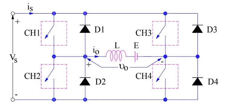
It consists of four semi conductor power switches named as CH1 to CH4 and four diods named as D1 to D4 are connected in anti parallel.
Four quadrant chopper circuit operation:
- For First quadrant operation: CH1 and CH4 is turn ON.
- For Second quadrant operation: CH2 only turn ON.
- For Third quadrant operation: CH3 CH2 is turn ON.
- For Fourth quadrant operation: CH4 only turn ON.
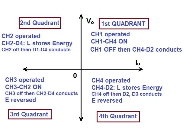
Comparison of Four quadrant chopper with BJT-H Bridge:
|
S.No |
Four Quadrant Chopper Drive |
BJT-H Bridge Drive |
|
1 |
In this thw motor can br operated in four different mode(Forward motoring, forward braking,reverse motoring,reverse breaking (or)regenerative braking |
In this the motor can be only operate in forward motoring and reverse motoring mode |
|
2 |
In this regenerative braking is achived. |
In this regenerative braking is not available. |
|
3 |
In this source is an fixed AC supply which can be rectified to DC supply. |
In this source is a fixed DC supply. |
|
4 |
The motor speed reference can be fed. |
Motor speed reference cannot be fed. |
|
5 |
Armature current shoot up during phase shift from positive to negative voltage is very low |
Armature current shoot up during phase shift from positive to negative voltage is high |
|
6 |
It will be helpful in better contorl of vehicle |
In terms of vehicle control this was low perfomance. |
|
7 |
It is using in industrial and commercial applications |
It is using for EV battery charging. |
2. Develop a 2-quadrant chopper using simulink & explain the working of the same with the relevant results. (Refer to article - Multiquadrant operation of motor )
This two quadrant chopper is also called as type C chopper. The reson for calling this as an two quadrant chopper it can operates only in two qudrants only it is shown below.
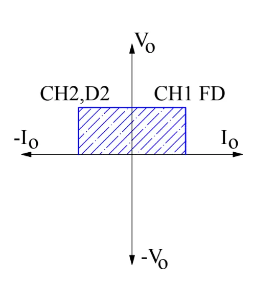
The circuit diagram of two quadrant chopper (or) type C chopper is shown below.
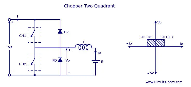
If we closely watch the circuit diagram we can understood this circuit is a cobination of type A & type B chopper circuits connected in parallel.
Type A chopper operates in first quadrant only and type B chopper operates in second quadrant only. So as a result of combining this two chopper circuits we can get the two quadrant chopper (or) type C chopper.
Operation of two quadrant chopper circuit:
One of the important point to keep remerber before operating the CH1 and CH2 is at a time only one chopper is need to turn ON or else it will lead to short circuit and the circuit get damaged.
I. Quadrant-1:
- In quadrant-1 chopper CH1 and freewheeling diode FD operates.
- When supply voltage Vs is given load current I from source flow through CH1-L-E and finally go to supply voltage (Vs) lower potential terminal and the circuit get closed.
- When the chopper CH1 gets turn OFF the freewheeling diode comes in action the load current from inductor load flow through FD.
- The load current Io from the inductor load and load current I form the voltage source will flows in same direction.
- So in this quadrant of operation both voltage and current are positive.
II. Quadrant-2:
- In quadrant-2 chopper CH2 and diod D1 operates.
- The load current flow toward toward source due to voltage (E) present at load side at this time source voltage is positive but load current from the inductive load is opposite to source voltage load current so at this quadrant current is negative. This load side voltage(E) must be half of the supply voltage.
Matlab simulation model for 2 Quadrant chopper is shown below:
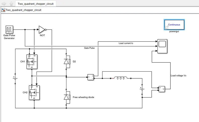
Simulink blocks used here:
- Power gui: This is used for simulation purpuse without this simulation won,t happen.
- Voltage & Current measurement Block: This blocks are used for measure load voltage (Vo) and load current(Io)
- DC Voltage source: This block is used for give DC voltage to the circuit. In this simulation we specfied DC voltage amplitude at source side 24V and at load side (E) 12V
- MOSFET: Two MOSFET are used for switching operation each named as CH1 and CH2. Inside the MOSFET parameter keep all other parameters as default only uncheck the check box at bottom show measurements port.
- Diod: Two Diods are used one is named as D2 and another one is named as freewheeling diode. Inside the Diode parameter keep all other parameters as default only uncheck the check box at bottom show measurements port.
- Series RLC branch: In series RLC branch parameter select branch type as L and keep other parameters as constant.
- Pulse Generator: This block is use to give pulse signal to CH1 and CH2 for switching operation.
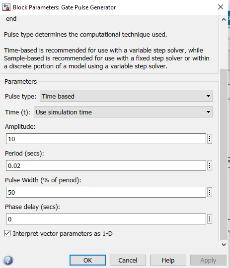
- Logical operator: In the parameter select the operator as NOT. Why because it will prevent the both CH1 and CH2 turn ON at a same time. It will prevent short circuit.
- Scope: This block is used to see the final output result.
Final output result;
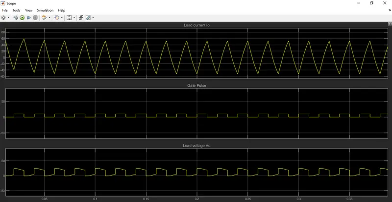
From the final output result of the two quadrant chopper it will be clearly understood the load voltage (Vo) is always positive and load current (Io) positive and negative alternatively.
3. Explain in a brief about operation of BLDC motor.
BLDC motor:
- Brushless DC (BLDC) motors also known as electronically commutated motors (ECMs, EC motors).
- Primary efficiency is a most importent feature for BLDC motors.
- Because the rotor is the sole bearer of the magnets and it doesn't require any power. i.e. no connections, no commutator and no brushes.
- In place of these, the motor employs control circuitry. i.e. electronic commutation.
Consturction of BLDC:
- In this motor, the permanent magnets attach to the rotor.
- The current-carrying conductors are located on the stator.
- BLDC motor use electrical commutation to convert electrical energy into mechanical energy.
- The main design difference between a brushed and brushless motors is the replacement of mechanical commutator with an electric switch circuit.
- In convensional DC motor when voltage is applied at no load condition it will works fine. But in BLDC motor when apply voltage at no load it won’t work. Why because in BLDC supply voltage terminal has three terminals then how do you connect a DC voltage source.
- So for this the third terminal is connected to electronic commutator.
- A BLDC Motor is a type of synchronous motor in the sense that the magnetic field generated by the stator and the rotor revolve at the same frequency.
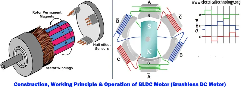
The layout of a DC brushless motor can vary depending on whether it is in “Out runner” style or “Inrunner” style.
- Outrunner – The field magnet is a drum rotor which rotates around the stator. This style is preferred for applications that require high torque and where high rpm isn’t a requirement.
- In runner – The stator is a fixed drum in which the field magnet rotates. This motor is known for producing less torque than the out runner style, but is capable of spinning at very high rpm.
Working Principle of BLDC:
- BLDC motor works on the principle similar to that of a convension brushed DC motor.
- The Lorentz force law which states that whenever a current carrying conductor placed in a magnetic field it experiences a force. As a consequence of reaction force, the magnet will experience an equal and opposite force.
- In the BLDC motor, the current carrying conductor is stationary and the permanent magnet is moving.
- When the stator coils get a supply from source, it becomes electromagnet and starts producing the uniform electromagnetic field in the air gap.
- Due to the force of interaction between electromagnet stator and permanent magnet rotor, the rotor continues to rotate.
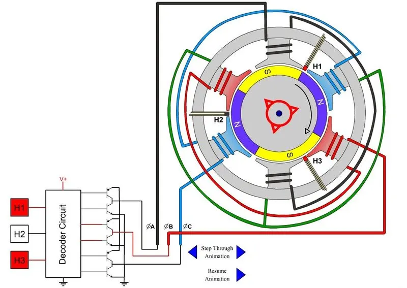
- With the switching of windings as High and Low signals, corresponding winding energized as North and South poles. The permanent magnet rotor with North and South poles align with stator poles which causes the motor to rotate.
- The switching of stator windings as high and low is taken care by Hall sensor.
- Most BLDC motors incorporate three Hall sensors which are embedded into the stator. Each sensor generates Low and High signals whenever the rotor poles pass near to it.
Advantages of Brushless DC motor:
- Less overall maintenance due to absence of brushes
- Reduced size with far superior thermal characteristics
- Higher speed range and lower electric noise generation.
- It has no mechanical commutator and associated problems
- High efficiency and high output power to size ratio due to the use of permanent magnet rotor
- High speed of operation even in loaded and unloaded conditions due to the absence of brushes that limits the speed
- Smaller motor geometry and lighter in weight than both brushed type DC and induction AC motors.
- Long life as no inspection and maintenance is required for commutator system
- Higher dynamic response due to low inertia and carrying windings in the stator
- Less electromagnetic interference
- Low noise due to absence of brushes
Limitations of Brushless DC motor
- These motors are costly
- Electronic controller required control this motor is expensive
- Requires complex drive circuitry
- Need of additional sensors
Applications of Brushless DC motor
- Computer hard drives and DVD/CD players
- Electric vehicles, hybrid vehicles, and electric bicycles
- Industrial robots, CNC machine tools, and simple belt driven systems
- Washing machines, compressors and dryers
- Fans, pumps and blowers.