Week -2
Part I: Make a Simulink model of Doorbell using solenoid block with the following details:
When the switch is closed the electromagnet receives electrical power from the battery and pulls the metal arm to hit the bell producing sound. Create a situation where the switch is closed for 2 seconds and then released. Observe the physical movement of the plunger.
Objective: The main aim of this Excercise is to create a simulink model for a Doorbell by using solenoid block.
1.First In Matlab tool bar i selected Simulink button
2. In Simulink i selected Blank model
3. I saved my Blank model in the name of Simulinkmodeldoorbell.
4. The given schematic diagram of Door bell arrangement is below.
From the given Door bell arrangement schematic diagam we can able to understand the door bell circuit consist of battery, switch, solenoid and a metal aram arrangement near to bell.
When the switch is closed the solinoid coil receives electrical power from the battery and pulls the metal arm to hits the bell and producing sound. Here in this case the switch closed for the time period of 2 sec.
5. Based on the given schematic diagram of Door bell arrangement I have selected the Electrical simulink blocks from simulink libray. Which is presented in the tool bar.
6. For this simullink model what are the simulink blocks i have used and its explanations given below for your reference.
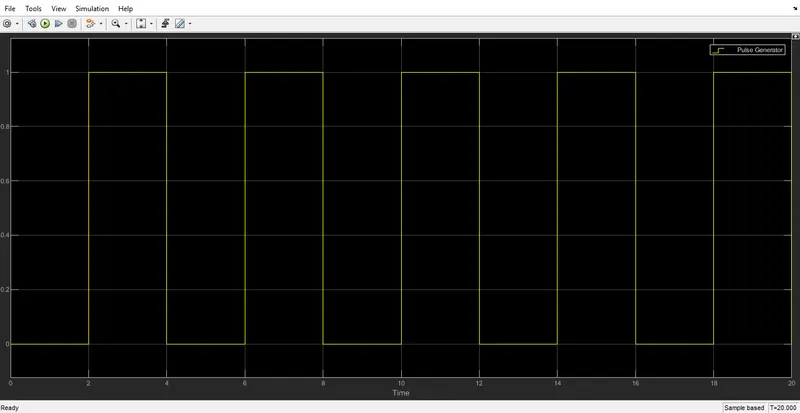
- Pulse generator - Use to give input pulse signal to close the switch in time interval of 2sec with specified amplitude=1,period=4sec, pulse widh=50%, phase delay=2 sec.
- Switch-Switch block controlled by an external physical signal. If the external physical signal PS is greater than the threshold, then the switch is closed, otherwise the switch is open.
- Battery- Use to give electric signal to solenoid block by series connection with switch.
- Solenoid- Use to convert electrical signal into mechanical motion/signal.
- Simulink to PS converter- Use to convert simulink input signal to physical signal.
- PS to Simulink converter- Use to convert physical input signal to simulink output signal .
- Electrical reference- Electrical reference port. A model must contain at least one electrical reference port (electrical ground).
- Mechanical translation reference- Used as a mechanical translational reference point, that is, a frame or a ground. Use it to connect mechanical translational ports that are rigidly affixed to the frame (ground).
- Solver configuration- This block specifies the solver parameters that your blocks need before begin the simulation.
- Ideal translation motion sensor- Used to convert an across variable measured between two mechanical translation nodes into a controlled signal propotional to velocity and position.
7. With help of the above mentioned Blocks i simulated the given Door bell schematic diagram.
8.Here i have represent my simulink model beow for your reference.
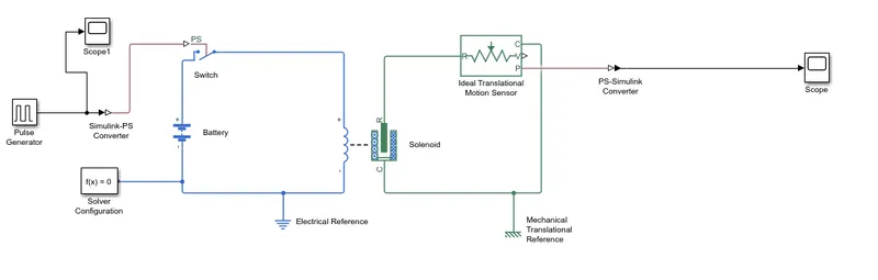
9. The above simulink model explanation:
- Pulse generator giving input pulse signal by using conveter block Simulink-PS signal to close the switch in time interval of 2sec with specified amplitude=1,period=4sec, pulse widh=50%, phase delay=2 sec.
- Switch block controlled by an external physical signal. If the external physical signal PS is greater than the threshold, then the switch is closed, otherwise the switch is open.
- Battery positive terminal is connected to switch block and negative terminal to the electrical reference.
- When the solenoid block connected with the battery and switch it forms a complete electrical circuit.
- Port C in the solenoid block connected with the mechanical translation reference and Port R in the solenoid block connected to the Ideal translation motion sensor to observe the position of the plunger.
- Scope is connected by using conveter block PS-simulink signal from ideal translation motion sensor to get the output.
- Solver configuration block specifies the solver parameters that your blocks need before begin the simulation.
10. Output results:
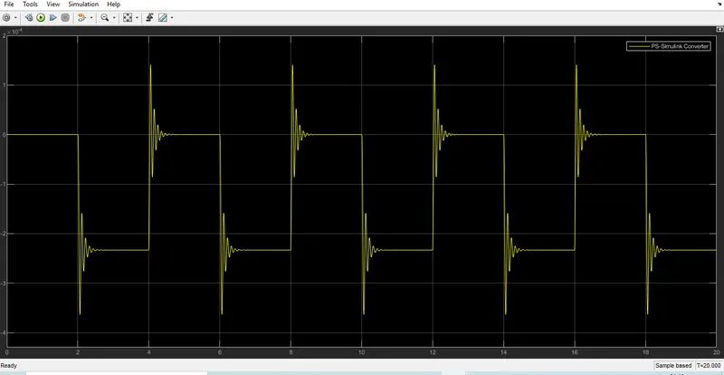
Here i run the simulation for 20sec. and obtained output results shown below.
11. Conclusion:
From the above scope solenoid output we can observe that at each 2 sec. the bell was ringing.
The simulink model for door bell is created and stuied.
Part II. Use a thermistor to sense the temperature of a heater & turn on or turn off the fan as per below conditions:
Temperature source: 20 °C from 0 to 10 seconds, 27 °C from 10 to 30 seconds, 23 °C from 30 to 50 seconds
Fan conditions: ON if the temperature above 25 °C, OFF otherwiseObjective: The main aim of this Excercise is to create a simulink model for by using thermistor to sense the temperature of a heater & turn on or turn off the fan as per condition. Fan condition will be ON if the temperature above 25 °C, OFF otherwise.
1.First In Matlab tool bar i selected Simulink button
2. In Simulink i selected Blank model
3. I saved my Blank model in the name of fancontroll.
4. For this simulink model what are the simulink blocks i have used and its explanations given below for your reference.
-
Controlled temprature source- used as an ideal energy source in a thermal network that can maintain a controlled temperature difference regardless of the heat flow rate. The temperature difference is set by the physical signal port S. A positive temperature difference causes the temperature at port B to be greater than the temperature at port A.
-
Thermistor- Used to sense the temprature change in heater
- Signal Builder - used to create desired signals and define the output waveforms. Here i have created the temprature source signals for the given conditions.(Point1 0 to 10 sec temperature will be 20deg=293K,Point2 0 to 10 sec temperature will be27deg=300K,Point1 0 to 10 sec temperature will be23deg=296K). Note: Here i have converted all the tempratures from degree celcius to Kelvin for simulation purpose.
- Switch- Pass through input 1 when input 2 satisfies the selected criterion; otherwise, pass through input 3. The inputs are numbered top to bottom (or left to right). The first and third input ports are data ports, and the second input port is the control port. The criteria for control port 2 are u2 >= Threshold, u2 > Threshold or u2 ~= 0. Here we found the threshold value of switch by connecting voltage sensor across resistor in the circuit.
- Battery- Use to give electric signal to fan temperature above 25 °C which means 298.15K
- Resistor- Used as reference resistence connect in series with thermistor, because there is no device measure resistance between the thermistor.
- Voltage sensor- used to sense the voltage drope across the thermistor for different temprature and to find the threshold droping voltage.
- Display - used to see the voltage drope across the thermistor.
- Simulink to PS converter- Use to convert simulink input signal to physical signal.
- PS to Simulink converter- Use to convert physical input signal to simulink output signal .
- Electrical reference- Electrical reference port. A model must contain at least one electrical reference port (electrical ground).
- Solver configuration- This block specifies the solver parameters that your blocks need before begin the simulation.
- Scope- Used to see the input temprature signal and final output result.
5. With help of the above mentioned Blocks i simulated this model.
6. Here i have represent my simulink model beow for your reference.
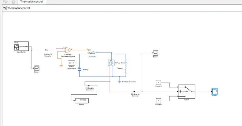
7. The above simulink model explanation:
- Here i have created the temprature source signals for the given conditions by using signal builder.(Point1 0 to 10 sec temperature will be 20deg=293K,Point2 0 to 10 sec temperature will be27deg=300K,Point1 0 to 10 sec temperature will be23deg=296K). Note: Here i have converted all the tempratures from degree celcius to Kelvin for simulation purpose.
- The created input temprature graph shown below.
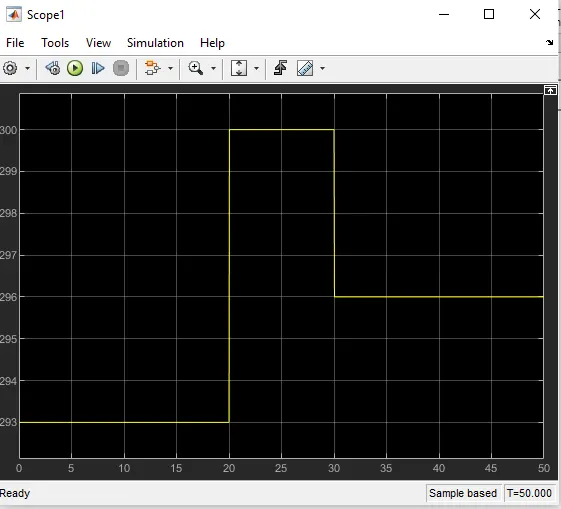
3. The created input temprature signal is converted into simulink to physical signal and then it is send to controlled temperature source to send and maintain a controlled temperature difference regardless of the heat flow rate.
4. Now the temprature signal is passed to thermistor to sense the change in temprature.
5. In order to run the fan when the temperature reached above 25 deg i.e.T>298.15K we connected a battery as a electrical supply source.
6. A resistor is connect in series with thermistor, because there is no device measure resistance between the thermistor.
7. voltage sensor to sense the voltage drope across the thermistor for different temprature and to find the threshold droping voltage. This voltage drop value is inputted as a threshold value for switch. Here below I showed graphical view of voltage drop across thermistor.

8. The output from the voltage sensor is connected to PS to Simulink converter to convert physical input signal to simulink output signal.
9. From the voltage sensor the converted simulink output signal is send to-
- Display to see the voltage drop across thermistor.
- Switch Pass through input 1 when input 2 satisfies the selected criterion; otherwise, pass through input 3. The inputs are numbered top to bottom (or left to right). The first and third input ports are data ports, and the second input port is the control port. The criteria for control port 2 are u2 >= Threshold, u2 > Threshold or u2 ~= 0. Here we found the threshold value form the display. ( Threshold value should be > 0.01099).
- Scope to see final output wheather the fan gets turn On and Off for the specified condition.
10. Output results:
Here i run the simulation for 50sec. and obtained output results shown below.
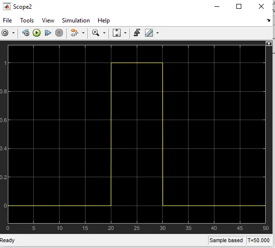
From the above graph we can clearly see that the fan will be Off condition for the time period of 0 to 20 sec. because the temperature at that time period is below 25 deg. i.e. T<298.15K and then the fan get turn On for the time period of 20 to 30 sec. because the temperature at that time period is above 25 deg. i.e. T>298.15K and then again the fan get turn Off for the time period of 30 to 50 sec. because the temperature at that time period is below 25 deg. i.e. T<298.15K.
11. Conclusion:
The simulink model for thermistor controlled automatic fan is created and stuied.