Week - 4
- Implement control logic of a “washing machine” using Stateflow as per given sequence:
- If the power supply is available, the system gets activated
- If the Water supply is not available, stop the process & indicate through LED
- Soaking time should be 200s followed by Washing time of 100s.
- Then rinsing happens for next 20s & dryer runs for 50s
Objective: The main aim of this Excercise is to create a control logic of a washing machine by using stateflow as per given sequence in above quesion.
1.First In Matlab tool bar i selected Simulink button
2. In Simulink i selected Blank model
3. I saved my Blank model in the name of Controll_logic_for_washingmachine.
4. The given sequence details.
- If the power supply is available, the system gets activated.
- If the Water supply is not available, stop the process & indicate through LED.
- Soaking time should be 200s followed by Washing time of 100s.
- Then rinsing happens for next 20s & dryer runs for 50s.
5.As per given sequence details i have created the stateflow chart. Here below i have attached the sateflow chart for your reference.
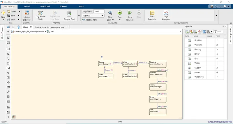
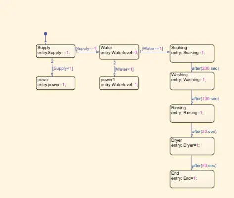
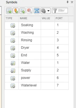
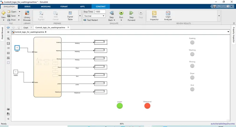
Here I have considerd water and supply as a input data and remaings soaking,washing,rinse dryer,end,power and waterlevel are considered as output data.
Here,
- End output data indicates the end of the sequence.
- Power output data indicates wheter the supply voltage is peresent .
- Waterlevel output data indicates wheter the water supply is present.
- All the output data's are connected with Display to see the status of the process. If the display shows 1 means the process is get started and completed and if it shows 0 means the process not get started due to initial conditions not satisfied.
6. Here below i shown the output results for the there conditions.
I. First condition: Supply voltage present, water supply present. Here all the Lamps are glowing in green color which means all the conditions are satisfied. Here all the output data's connected with display shows 1 which means the process get started and completed which means all the initial conditions are satisfied.
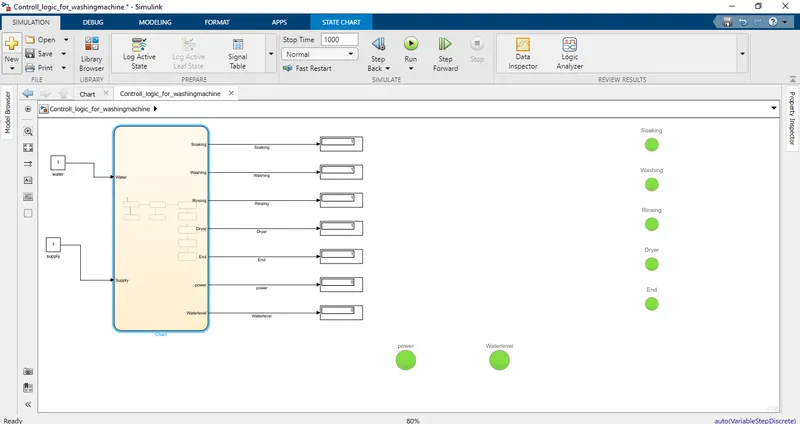
II. Second condition: Supply voltage is not present, water supply present. Here Power Lamp is glowing in red color because obsense of supply voltage,waterlevel lamp is glowing in green color because water supply is present and remaing lamps are not glowing which means the supply voltage is not present due to that the remaing process are stopped. Here all the output data's connected with display shows 0 which means the process not get started due to initial conditions not satisfied.
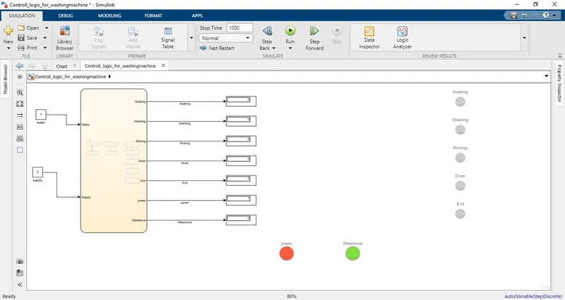
III. Third condition: Supply voltage is present, water supply is not present. Here Power Lamp is glowing in green color because of supply voltage is present,waterlevel lamp is glowing in red color because water supply is absent and remaing lamps are not glowing which means the water supply is not present due to that the remaing process are stopped.Here all the output data's connected with display shows 0 which means the process not get started due to initial conditions not satisfied.
Conclusion: The simulink model and a control logic for a washing machine by using stateflow as per given sequence is created and studied.
2. Make a Simulink chart for the “Gear shift” logic as per below conditions:
Speed Range(kmph) Gear
0 to 15 1
16 to 25 2
26 to 40 3
41 to 60 4
Above 61 5
Give speed input while the simulation is running & display the gear number.
Objective:The main aim of this Excercise is to create a control logic for a Gear shift as per given above conditions.
1.First In Matlab tool bar i selected Simulink button
2. In Simulink i selected Blank model
3. I saved my Blank model in the name of Simulink_chart_for_gearshift.
4. The given conditions details.
Speed Range(kmph) Gear
0 to 15 1
16 to 25 2
26 to 40 3
41 to 60 4
Above 61 5
5.As per given conditions details i have created the stateflow chart. Here below i have attached the sateflow chart for your reference.
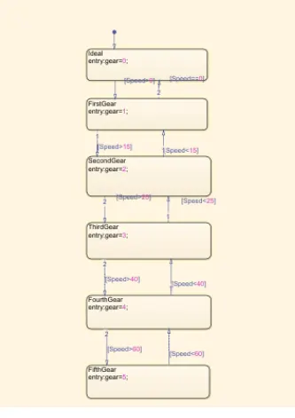
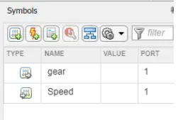
Here I have considerd speed as a input data and gear as output data.
Here,
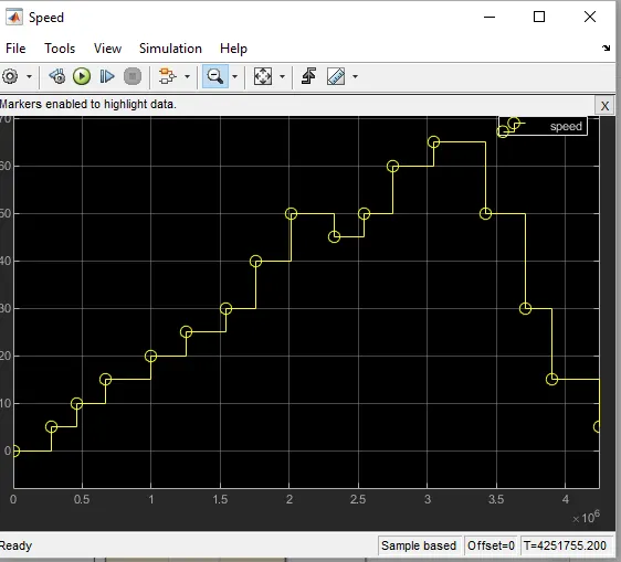
I have used slider gain block as accelerator to varying the input speed and Scope block to see the input varying speed and output gearshift according to the speed conditions mentioned in the state flow chart.
6.Below I have attached the simulink model for gear shift.
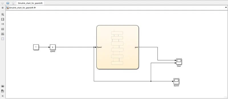
7. Below I have attached the scope output result for varying input speed from slider gain block.
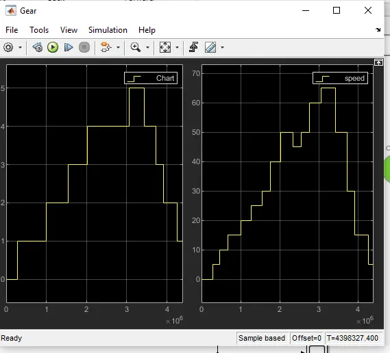
7.Below I have attached the scope output result for gear shift as per speed conditions mentioned in the state flow chart.
In this first picture on left side shows gear status and second picture on right side shows input speed. According to the graph for diffrend speed conditions the gear gets change.
Conclusion: The simulink model and a control logic for a Gear shift was created as per given conditions and studied.