Week-7 Challenge: DC Motor Control
1A ) Here the simulation of a “Speed control of a DC motor using BJT H-Bridge” has been discussed.
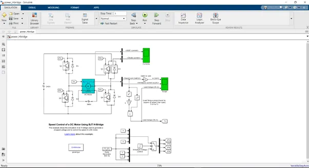
From the Simulink model, we can infer that
- Here 4 IGBT switches are used, each of which is triggered using a separate PWM signal, having a duty ratio of 75%.
- The switching circuitry is implemented using bus and a demux. Since at a time only two switches need to be active, this principle is implemented by selecting two PWM waveforms.
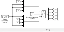
There are two groups of signals. Group one has signals for switches Q2 and Q3. And the second group has signals for switches Q1 and Q4. Depending upon the sequence, the respective group of signals are selected to trigger the switches.
This section deals with the speed control of the DC motor, since the PWM signals generated from here is used to trigger the IGBT switches.
- The power supply of 240V is being transferred to the load(motor) via H- Bridge, where out of four switches, 2 switches work simultaneously in the two modes of operation.
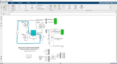
MODE 1 - With respect to the switching sequence mentioned above, the current follows the path as shown above: Source-Q1-load-Q4-Source.
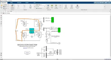
MODE 2 - With respect to the switching sequence mentioned above, the current follows the path as shown above: Source-Q2-load-Q3-Source.
As evident, the direction of current is just opposite to one another in each of the mode of operation.
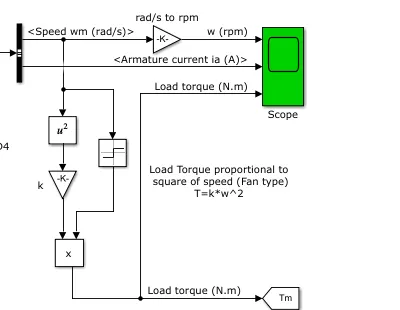
- Results have been shown in two different scopes. The first scope presents the currents of the IGBT and diode switches. The second scope presents the motor characteristics like Armature current in A, speed of the motor in rad/s which is also converted to rpm and the Load torque in Nm, using the Speed-torque relation (T=k*w2)
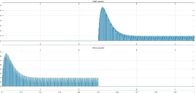
- From graph1 we can deduce the switching on and off of the IGBT and the diode switches.It is evident that when the IGBT is on the diode is reverse biased and does not conduct and giving zero current whereas in the second cycle when IGBT is off the diode is in conducting mode and in freewheeling mode and we can see similar current in both switches.
Also from graph 2 we can conclude that during the on condition of the IGBT switch the speed reaches to a max value after an amount of rise time of 0.1 sec and it becomes equal to zero when the IGBT is in off condition.
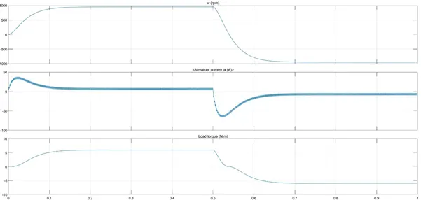
Same can be said for the torque characterstics but the torque graph goes to equivalent negative value during OFF time which indicated regenerative e mode and the path for the same is provided by the freewheeling diodes.
1b) The spike in the current is because in series DC motor there is very high intial torque which leads to high current generation because T = flux*current.
So in series motor starting condition we always should use minimum load to avoid this high surge in current.
Also if the Duty ratio is decreased, which results in low voltage , the torque produced will be less and hence the surge in current will be minimal.
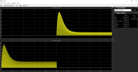
1c) The Four-Quadrant Chopper DC Drive (DC7) block
In this circuit the input is basically derived from an AC supply which is then converted to DC voltage which is then passed to the DC7 block.
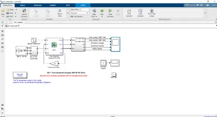
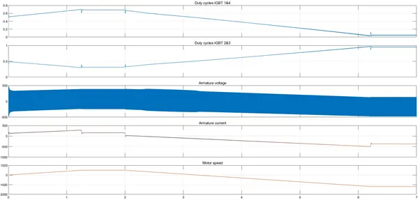
Here instead of PWM, reference speed is used for varying the speed and torque of the motor.
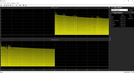
It is because of this, the IGBT currents have different waveform in comparison to one against the current waveform of H bridge.
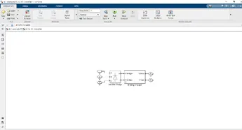
The AC – DC converter is implemented using rectifier for converting AC to DC and the a DC chopper is used to bring the DC voltage to a desired level.
Comparison of The Four-Quadrant Chopper DC Drive (DC7) block with H-bridge
The Four Quadrant Chopper DC Drive operates in four modes wiz. forward motoring, forward regenerative braking, reversing motoring and reverse regenerative braking mode whereas BJT H-Bridge model operates only on two modes wiz. forward and reverse.
The simulation time is less in H-bridge when compared to DC7 block because H-bridge uses continuous simulation in contrast to discrete in 4 quad DC drive
Direction of the motor rotation can be changed by changing the polarity in a H-bridge structured circuit whereas in 4 quad chopper DC drive the direction of the motor can be changed in a by changing the input signal to the DC7 block.
Speed of the motor in H-bridge circuit can be varied by varying the duty cycle of the motor but in the DC drive with DC7 block speed of the motor is varied by the input signal or speed reference.
H-bridge circuit does not require the use of snubber but it is required for the DC7 block. This is due to the rapid raise in the voltage when a change in the input signal occurs in the DC7 block.
The overall performance and stability is good in Four Quadrant Chopper DC Drive comparing BJT H-Bridge model.
2) Class-C or Type-C Chopper is a category of chopper which can operate in first as well as second quadrant. This basically means that, the power can either flow from source to load or load to source in this chopper.
Class-C or Type-C chopper is obtained by the parallel connection of Class-A and Class-B chopper. Figure below shows the circuit diagram of this type of chopper.
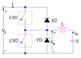
In chopper CH1, free-wheeling diode (FD) and load are forming Class-A Chopper whereas chopper CH2, D2 and Load are forming Class-B chopper. Both these choppers are connected in parallel. To obtain first quadrant operation we should switch ON chopper CH1 and for getting second quadrant operation we should switch ON chopper CH2.
Case-1: When CH1 is switched ON / OFF
When chopper CH1 is switched ON, source Vs directly gets connected to the load and hence, load voltage Vo is equal to source voltage. The direction of load current is from source to load as shown in the circuit diagram which is assumed positive.
When CH1 is switched OFF, the free-wheeling diode FD comes into the circuit as it gets forward biased and hence shorts the load. Therefore, the output voltage Vo becomes zero. However, the io continues to die down through the FD and L in the same direction as shown in circuit diagram.
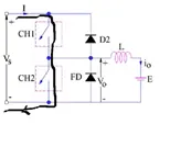
Thus, the average output voltage Vo and current Io are positive and hence operation of chopper is in first quadrant. In fact, this is the Class-B mode of operation.
Case-2: When CH2 is switched ON / OFF
When chopper CH2 is switched ON, load DC source E drives current through CH2 and load. The direction of this current io will be opposite to that shown in circuit diagram and hence is assumed negative. Output voltage Vo is zero during this time.
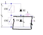
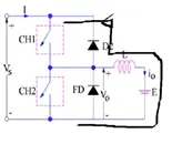
When CH2 is made OFF, diode D2 gets forward biased and hence the current into the source from the load. The output voltage is Vs in this time as the load is connected to the source through D2 during OFF time of chopper CH2. Thus, the load current is always negative i.e. operation of chopper is within second quadrant. In fact, this is the Class-B mode of operation.
Now implementing two quadrant chopper in Simulink
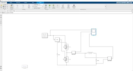
Steps to derive the model
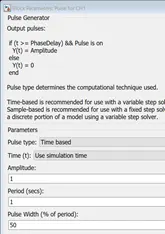
1) Pwm generator is selected and then a desired duty cycle is selected. Here i have selected a duty cycle of 50%
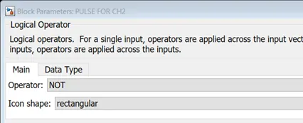
2) Since we have to supply gate signal to 2 different chopper with a phase difference of 180, a not logic operator is selected by selecting the logic operator block and then selecting the NOT option
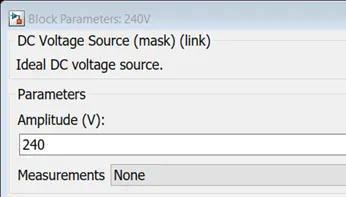
3) After selecting the gate , two DC power supplies have been selected with a value of 240V
4) Next we select the semiconductor switch IGBT with snubber as RC also a diode.
5) Then we have to select the load or inductor for that we select the RLC block and from its properties we select the L
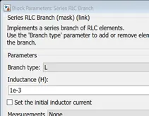
6) Then we get a current and voltage measurement along with scope for viewing the graph.
7) After getting all the components they all are connected according to the connection shown above and the simulation is run for 20 time period.
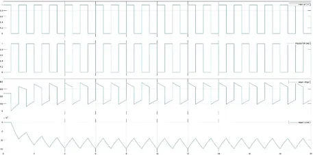
From the above two GRAPH, we can conclude the following points:
The PWM signals for CH! & CH2 are inverted.
The output voltage Vo is going to zero when chopper CH2 is ON or free-wheeling diode FD conducts.
The output voltage Vo is becoming equal to source voltage Vs when chopper CH1 is ON or diode D2 conducts.
The average load voltage is always positive but the average load current may be positive or negative. Therefore, power flow may be from source to load (first quadrant operation) or load to source (second quadrant operation). The operating region of Class-C or Type-C chopper is shown below by hatched area.
3) What is a Brushless Motor?
A Brushless DC Motor is similar to a Brushed DC Motor but as the name suggests, a BLDC doesn’t use brushes for commutation but rather they are electronically commutated. In conventional Brushed DC Motors, the brushes are used to transmit the power to the rotor as they turn in a fixed magnetic field.
A brushless DC motor is an electronically commuted DC motor which does not have brushes. These types of motors are highly efficient in producing a large amount of torque over a vast speed range. In brushless motors, permanent magnets rotate around a fixed armature.
Construction of BLDC Motor
It’s major components comprise:
- an armature or rotor made of permanent and in many cases neodymium magnets; and
- a stator with windings that create a magnetic field when energized.
As you can see in the image, a BLDC Motor consists of two main parts: a stator and a rotor.
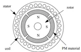
The main design difference between a brushed and brushless motors is the replacement of mechanical commutator with an electric switch circuit. Keeping that in mind, a BLDC Motor is a type of synchronous motor in the sense that the magnetic field generated by the stator and the rotor revolve at the same frequency.
Brushless Motors are available in three configurations: single phase, two phase and three phase. Out of these, the three phase BLDC is the most common one.
Stator
The structure of the stator of a BLDC Motor is similar to that of an induction motor. It is made up of stacked steel laminations with axially cut slots for winding. The winding in BLDC are slightly different than that of the traditional induction motor.
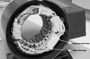
Stator of a BLDC motor made up of stacked steel laminations to carry the windings. These windings are placed in slots which are axially cut along the inner periphery of the stator. These windings can be arranged in either star or delta. However, most BLDC motors have three phase star connected stator.
Rotor
The rotor part of the BLDC Motor is made up of permanent magnets (usually, rare earth alloy magnets like Neodymium (Nd), Samarium Cobalt (SmCo) and alloy of Neodymium, Ferrite and Boron (NdFeB)).
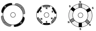

Based on the application, the number of poles can vary between two and eight with North (N) and South (S) poles placed alternately. The following image shows three different arrangements of the poles. In the first case, the magnets are placed on the outer periphery of the rotor.
Position Sensors (Hall Sensors)
A Position Sensor, which is usually a Hall Sensor (that works on the principle of Hall Effect) is generally used to detect the position of the rotor and transform it into an electrical signal. Most BLDC Motors use three Hall Sensors that are embedded into the stator to sense the rotor’s position.
Working Principle
BLDC Motor Controller Circuit Design
In a normal DC motors, there are permanent magnets on the outside and a spinning armature which contains electromagnet is inside. These electromagnets create a magnetic field in the armature when the power is switched on and help to rotate the armature.
The brushes change the polarity of the pole to keep the rotation on of the armature.
In BLDC permanent magnets are attached in the rotor and move the electromagnets to the stator. The high power transistors are used to activate electromagnets for the shaft turns. The controller performs power distribution by using a solid-state circuit.
BLDC motor works on the principle similar to that of a conventional DC motor, i.e., the Lorentz force law which states that whenever a current carrying conductor placed in a magnetic field it experiences a force. As a consequence of reaction force, the magnet will experience an equal and opposite force. In case BLDC motor, the current carrying conductor is stationary while the permanent magnet moves.
Consider the following setup of three windings in the stator designated A, B and C. For the sake of understanding, let us replace the rotor with a single magnet.
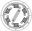
We know that when a current is applied through a coil, a magnetic field is generated and the orientation of the field lines i.e. the poles of the generated magnet will depend on the direction of the current flowing through the coil.
Using this principle, if we supply current to the coil A so that it will generate a magnetic field and attract the rotor magnet. The position of the rotor magnet will shift slightly clockwise and will align with A.
If we now pass current through coils B and C one after the other (in that order), the rotor magnet will rotate in clock wise direction.
To increase efficiency, we can wind the opposite coils using a single coil so that we get double attraction. Further increasing the efficiency, we can energize two coils at the same time so that one coil will attract the magnet and the other coil will repel it. During this time, the third will be idle.
For a complete 360 degree rotation of the rotor magnet, six possible combinations of the coils A, B and C are applicable and are shown in the following timing diagram.
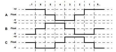
Based on the above diagram, we can confirm that at any time, one phase is positive, one phase is negative and the third phase is idle (or floating). So, based on the inputs from the Hall Sensors, we have two switch the phases as per the above diagram.
Brushless DC Motor Drive
A typical BLDC motor controller has a half-bridge or half-H bridge circuit. Unlike an H bridge, this circuit configuration has only two switches - one high-side and one low-side transistor.
Most brushless motors use two or three-phase power systems. So in a BLDC motor controller circuit diagram, this will look like two or three half-bridges (depending on the number of phases) with a pair of switches each.
In this 3 phase brushless DC motor controller with Hall-effect sensors to view the basic principles of its circuit design.
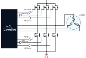
- The stator has three-phase windings located at 120° to one another. Each winding has a vector representation of voltage and current applied to the stator.
- The BLDC motor controller Hall sensors identify the rotor’s position. Upon receiving the sensor data, the power MOSFETs switch the current, injecting it into the right winding. In a high power brushless DC motor controller, IGBTs and GaN switches can replace MOSFETs.
- Either integrated or discrete gate drivers can control the transistors. The drivers of a brushless motor controller schematic act as intermediaries between the switches and a microcontroller (MCU).
- The three-phase BLDC motor controller circuit includes six steps necessary to complete a full switching cycle (that is to energize all the three windings of the stator). By turning the high-side and low-side transistors on and off, the current flows through the stator windings in sequence.
- With the trapezoidal commutation, two windings out of three can stay energized at the same time. In the sinusoidal control method, the phase shift complies with the law of sines. It provides smoother current switching between the phases.The trapezoidal commutation is simpler, but it may cause the vibration of the motor at low speeds.
- Typically, a sinusoidal brushless motor controller circuit uses pulse-width modulation (PWM). It helps regulate the current injected into the rotor’s windings and run the commutation process more smoothly and efficiently. This applies specially to closed-loop controllers that get feedback on the output signal and adjust the input power by varying the duty cycle.
- The electronic controller circuit energizes appropriate motor winding by turning transistor or other solid state switches to rotate the motor continuously. The figure below shows the simple BLDC motor drive circuit which consists of MOSFET bridge (also called as inverter bridge), electronic controller, hall effect sensor and BLDC motor.
- Here, Hall-effect sensors are used for position and speed feedback. The electronic controller can be a microcontroller unit or microprocessor or DSP processor or FPGA unit or any other controller. This controller receives these signals, processes them and sends the control signals to the MOSFET driver circuit.
- In addition to the switching for a rated speed of the motor, additional electronic circuitry changes the motor speed based on required application. These speed control units are generally implemented with PID controllers to have precise control. It is also possible to produce four-quadrant operation from the motor whilst maintaining good efficiency throughout the speed variations using modern drives.