Week -2
- Make a Simulink model of Doorbell using solenoid block
For implementing , following steps have been followed
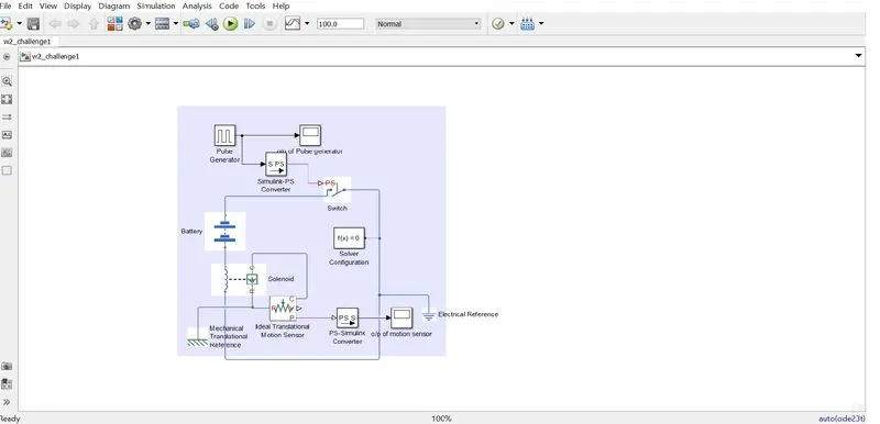
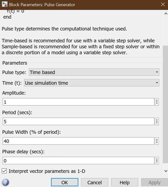
- For the requirement of the switch being closed for 2 seconds and then released, a pulse generator is used with time period of 5 sec and duty ratio of 40% which would result in on time of 2 sec and off time of 3 sec.
- The generated pulse is then being given as input to the a switch which is controlled by an external physical signal, via simulink to PS converter.
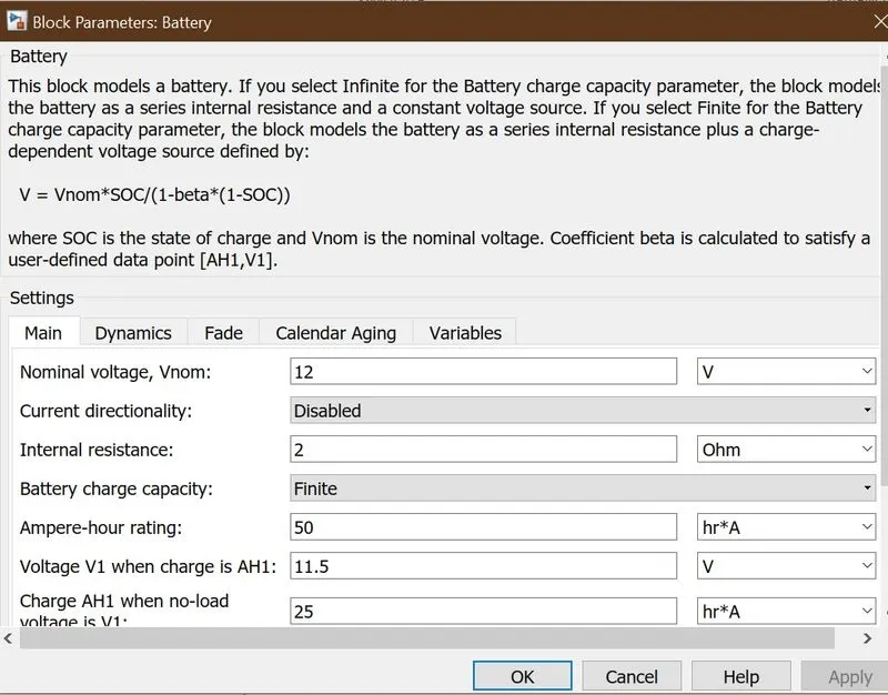
- The switch, at one end is connected to one terminal of solenoid via battery and the other end is connected to other terminal of solenoid. To this connection , solver configuration and electrical reference are also connected.
- The Port R & C of solenoid is connected to Port R & C of Ideal Translational Motion sensor respectively.
- As we need to movement of hammer to hit the bell which is a linear motion we have used Ideal Translational Motion sensor. The physical signal port P which report the position, is connected to the sccope for observing the output via PS to simulink converter.
- GRAPH
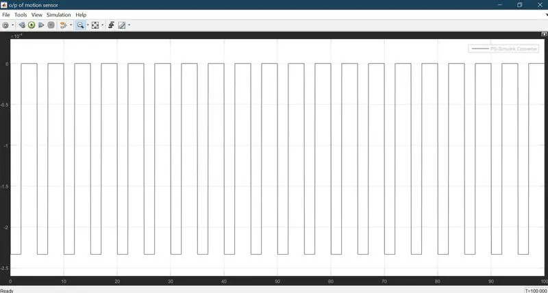
- In the simulation , 2 grpahs have been observed.
- 1st is the graph for pulse generator showing the implementation of 2 sec switch off criteria.
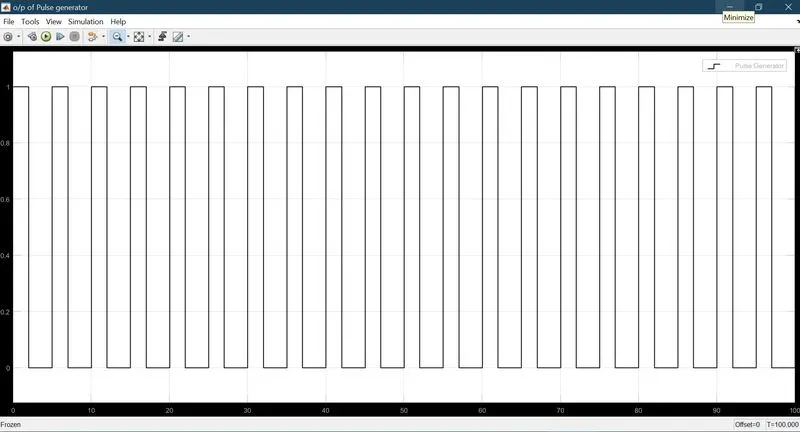
- Here we can see that the simulation run time of 100 sec, everry pulse is of duration of 5 sec with 2 sec on time and 3 sec off time.
- 2nd graph shows the output of translational motion sensor which shows the varation according to pulse generator's variation.
2) Use a thermistor to sense the temperature of a heater & turn on or turn off the fan
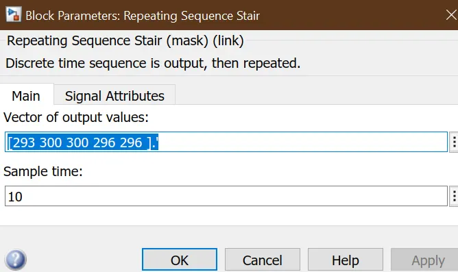
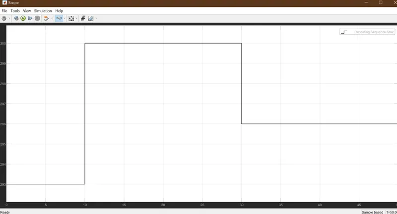
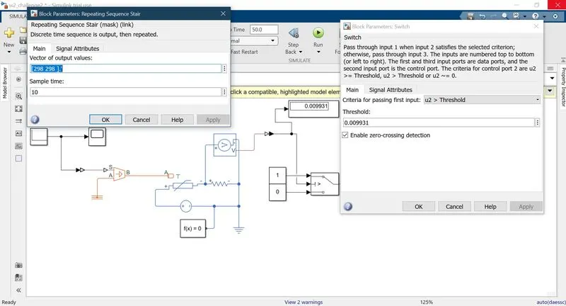
- As per the requirement of variable temperature for different time periods, repeating sequence stair is used which provides the flexibility of sample time and multiple inputs in form of vector, where each vector element is implemented at regular sampled time.
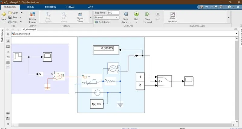
- The ouput of sequence stair , which being a constant value , is given to port B of controlled temperature source via Simulink to PS converter. Controlled temperature source is used as it provides flexibilty of providing varying temperature range in accordance to the variation produced by sequence pair. Port S of controlled temperature source is cconnected to the port T of thermister , which is powered by a DC voltage source placed in series with 1 ohm resistor.
- This 1 ohm resitor is used for connecting a voltage sensor in order to get the voltage value equivalent to 25 degrees, which is criteria for switching on the fan.
- This value of voltage is used as thershold value in the switch. Switch is having 3 inputs one is 1 and the other is 0. whenever the input of switch is greater than the set threshold value the output is 1 else its 0.
- For me, the thershold value came to be 0.00931
GRAPH
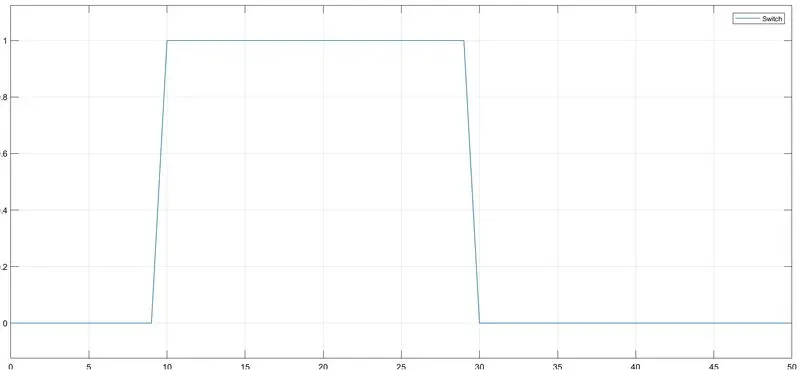
- From the graph we can deduce that the output of switch is 1 only when the temperature is greater than 25 , after comparison with output of sequence pair we can infer that the temp is high during the time duration of 10 to 30 , hence the output of switch is 1 for almost same time.
- So we can deduce that the fan is on only when the temp is greater than 25.