Week-7 Challenge: DC Motor Control
1. A. Explain a MATLAB demo model named ‘Speed control of a DC motor using BJT H-bridge.
This model aims at cotrolling the speed of DC motor using a DC-DC chopper.
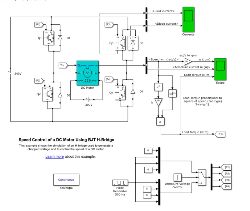
- The Chopper circuit shifts down supply voltage, it uses IGBT block but the functioning of IGBT block here is as BJT block as operating characterstic of BJT and IGBT are similar in saturation region. The trigering of these switches is controlled by Simulink Signal.
- The output of the H-bridge are connected to the DC motor model (5HP 24V 1750rpm), here the load is taken as a fan type load(load torque is directly proportional to square of angular speed)
- The Pulse Generator block controls the H-bridge by defining the duty cycle of the chopper circuit.
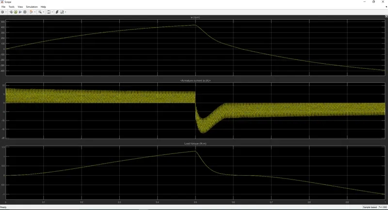
B. Comment on the armature current shoot-up from the scope results.
The current shoot up we observe is due to the PWM switching that we are using;
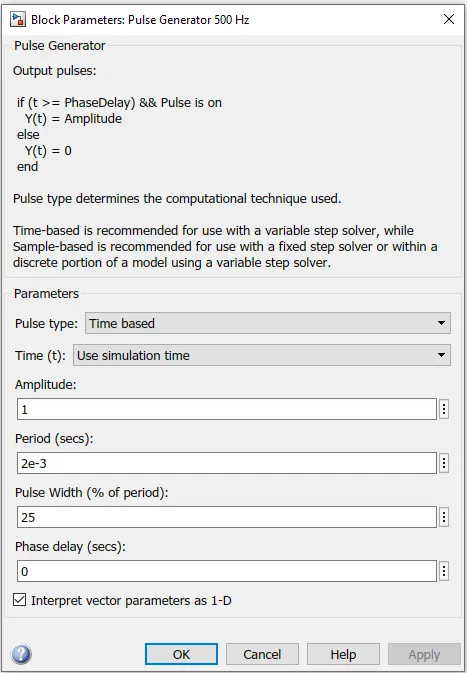
hence we try on to vary the pulse width percentage of the Switching scheme and try to find out if there are some changes.
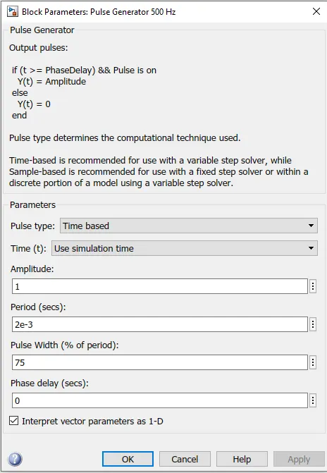
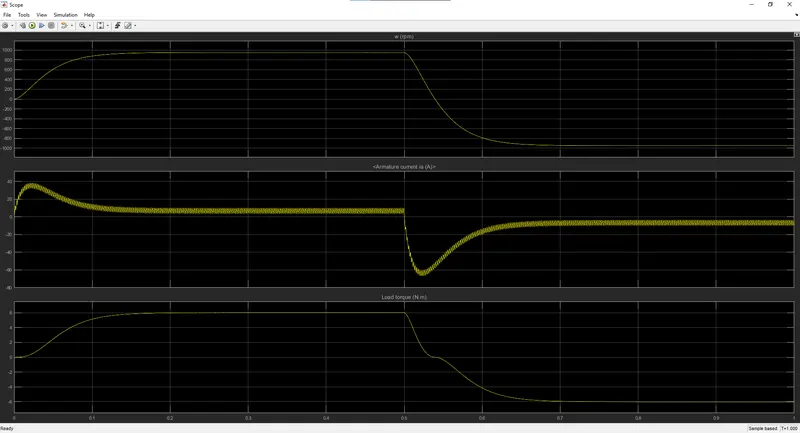
When we decrease the pulse width percentage the current shoot up seems to decrease,
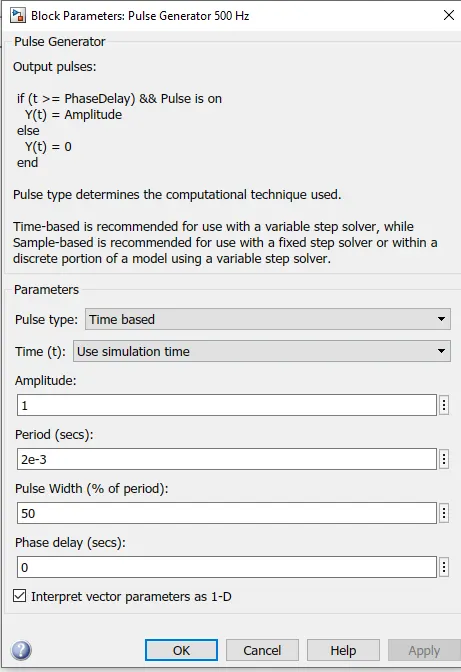
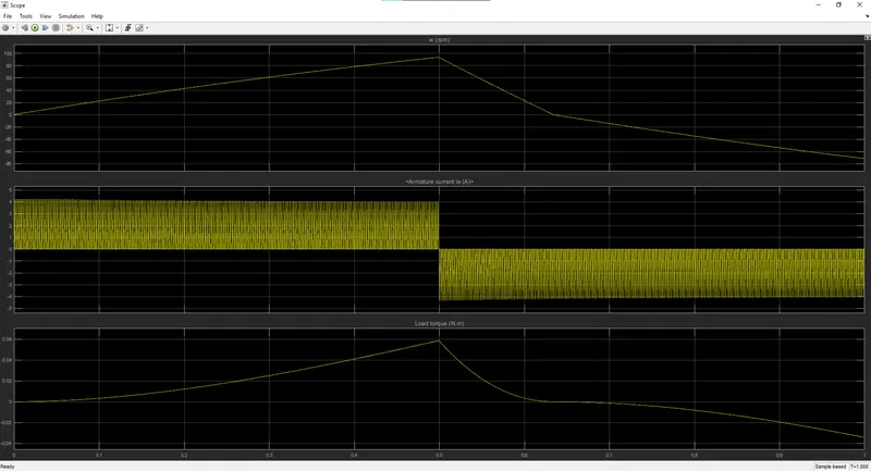
And at 25%:
C. Refer to the help section of ‘The Four-Quadrant Chopper DC Drive (DC7) block’. Compare it with the H-bridge model.
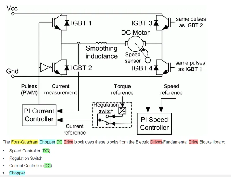
fig:Four-Quadrant Chopper DC Drive (DC7)
| DC7 Block | H-bridge model |
| 1. It is a single drive model in Simulink which has both the converter and motor inside it. | 1. This is a large simulink arrangement of different block to showcase the speed control of DC motor using converter circuit. |
| 2. Parameters can be varied through various tabs like motor tab, converter tab etc. |
2. All the parameters can be varied into their respective subsystems like Pulse generator block, DC motor block etc. |
| 3. It is a closed loop circuit. | 3. It is an loop circuit, since it has feedback for reference speed. |
2. Develop a 2-quadrant chopper using simulink & explain the working of the same with the relevant results. (Refer to article - Multiquadrant operation of motor )
We can design a two-quadrant chopper in simulink following the its theory as follows:
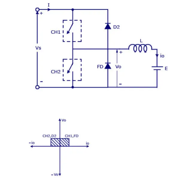
applying in Simulink;
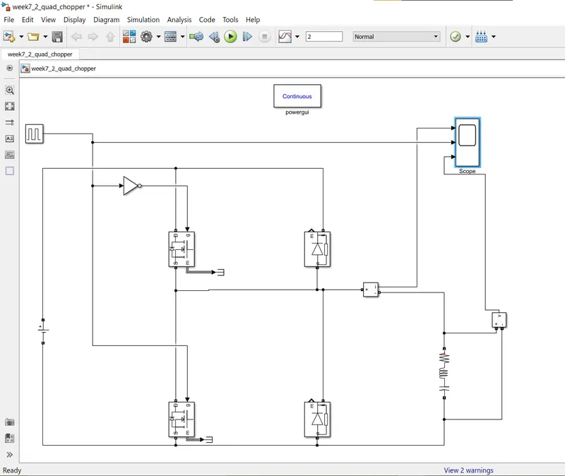
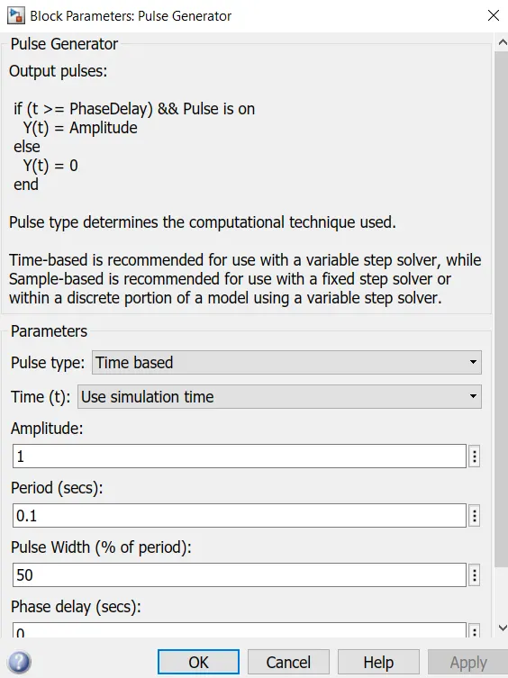
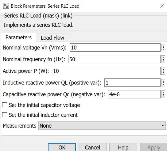
And upon selecting appropriate parameters,
we get results like this on scope.
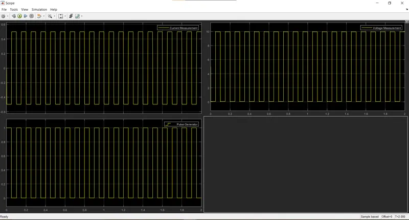
As we can see in the scope that the waveforms of Current are both positive and negative but the voltage always remains positive; hence this circuit successfully performs as a two-quadrant chopper.
3. Explain in a brief about operation of BLDC motor.
Brushless DC electric motors also known as electronically commutated motors (ECMs, EC motors).
In this motor, the permanent magnets attach to the rotor. The current-carrying conductors or armature windings are located on the stator. They use electrical commutation to convert electrical energy into mechanical energy.
The main design difference between a brushed and brushless motors is the replacement of mechanical commutator with an electric switch circuit. A BLDC Motor is a type of synchronous motor in the sense that the magnetic field generated by the stator and the rotor revolve at the same frequency.
BLDC motor works on the principle similar to that of a Brushed DC motor. The Lorentz force law which states that whenever a current carrying conductor placed in a magnetic field it experiences a force. As a consequence of reaction force, the magnet will experience an equal and opposite force. In the BLDC motor, the current carrying conductor is stationary and the permanent magnet is moving.
When the stator coils get a supply from source, it becomes electromagnet and starts producing the uniform field in the air gap. Though the source of supply is DC, switching makes to generate an AC voltage waveform with trapezoidal shape. Due to the force of interaction between electromagnet stator and permanent magnet rotor, the rotor continues to rotate.
With the switching of windings as High and Low signals, corresponding winding energized as North and South poles. The permanent magnet rotor with North and South poles align with stator poles which causes the motor to rotate.
Brushless motor does not have any current carrying commutators. The field inside a brushless motor is switched through an amplifier which is triggered by the commutating device like an optical encoder.
The layout of a DC brushless motor can vary depending on whether it is in “Out runner” style or “Inrunner” style.
-
Outrunner – The field magnet is a drum rotor which rotates around the stator. This style is preferred for applications that require high torque and where high rpm isn’t a requirement.
-
In runner – The stator is a fixed drum in which the field magnet rotates. This motor is known for producing less torque than the out runner style, but is capable of spinning at very high rpm.
-Source: robu.in