Week-7 Challenge: DC Motor Control
AIM:
To study power electronics of DC motor which includes power converters and also control of DC motor using the power circuits in Simulink.
OBJECTIVES:
- To study and run the MATLAB demo model of Speed control of DC motor using BJT(Bipolar junction transistor) H bridge in Simulink and comment on the armature current shoot up from scope.
- To study and refer to the ‘The Four-Quadrant Chopper DC Drive (DC7) block' from Simulink and compare it with the H bridge.
- To develop 2 quadrant chopper in Simulink and explain its working with studied results.
- To study the operation of BLDC(Brushless DC motor).
CASE STUDY 1:
Study and run the MATLAB demo model of Speed control of DC motor using BJT(Bipolar junction transistor) H bridge in Simulink and comment on the armature current shoot up from scope.
To study the model of speed control of DC motor using BJT H-bridge or IGBT(Insulated gate bipolar transistor) we got to know what are all the basic components used inside the circuit in order to control the voltage, Current, Torque, speed. Power switches are used to control the electronic signals(control signals) which is given to the power circuits(To get the required voltage and current). The main components are BJT simulated by IGBT and diodes.
Bipolar Junction Transistor(BJT):
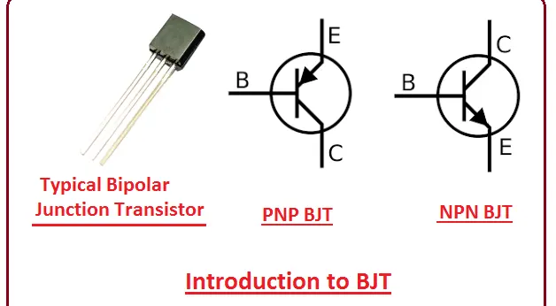
A bipolar junction transistor(BJT) is used to control the amount of current flowing through the emitter and collector terminals which is dependent on the amount of biasing voltage applied at the terminal. This is acts like a current-controlled switch. Here we are using the N-P-N transistor.
Insulated Gate Bipolar transistor(IGBT):
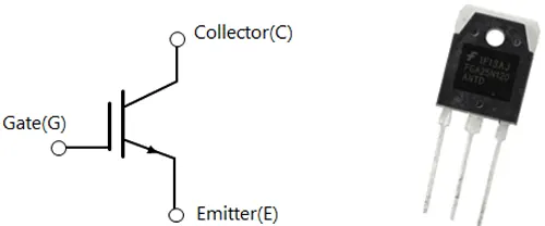
IGBT is a bipolar transistor with an insulated gate. IGBT a single device that combines both control input of the MOS structure and bipolar power transistor that acts as an output switch. IGBT's are mainly used for high voltage and high current applications. IGBT is a semiconductor with three terminals that work with a switch for moving electric current. The three terminals of IGBT are Gate, Emitter, collector. When the voltage is applied at the gate terminal which in turn opens or 'turns ON' to create a path for current flow between the layers. If there is no voltage applied at the gate then the voltage is not sufficient enough to open the gate hence the is no flow of electricity. IGBT acts like a switch to create Pulse width modulation(PWM). This IGBT switch is so rapid where switching of current ON and OFF wherein less voltage is channeled into the DC motor.
DIODE:
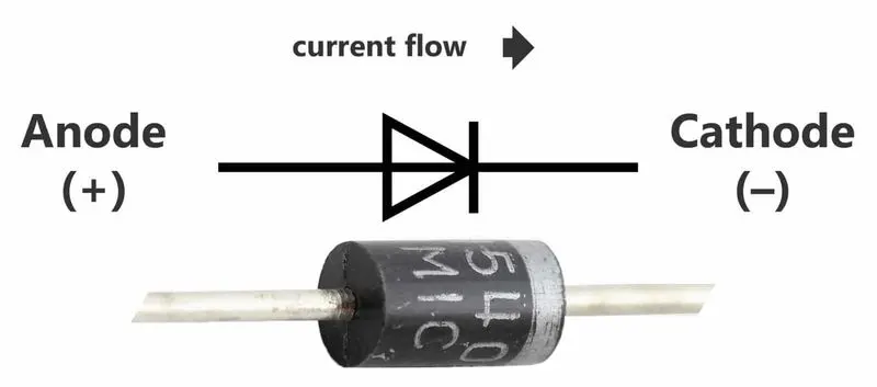
A diode is used to control the direction of current flowing inside the circuit.
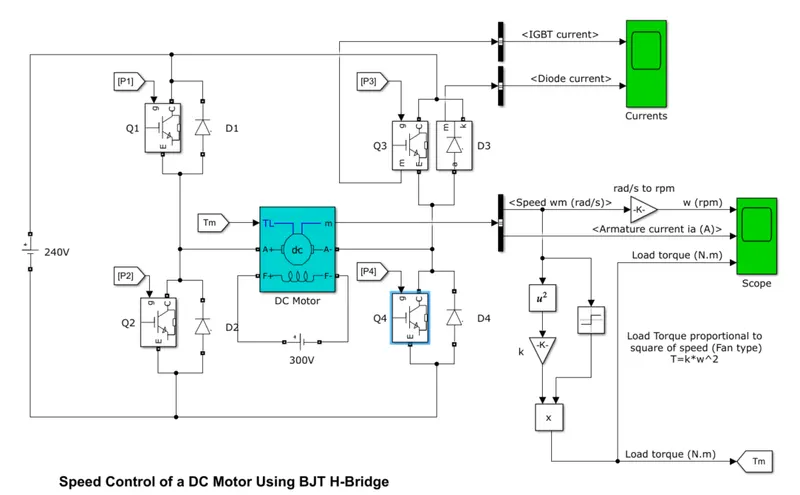
Speed control of DC motor using BJT simulated by IGBT models consists of 4 IGBT switches(Q1, Q2, Q3, Q4) and 4 diodes(D1, D2, D3, D4) which are arranged in H-Bridge circuit. The armature voltage is varied from 0 to 240 volts based on the duty cycle specified by the pulse generator block(varied from 0-100%). In the above model, two-transistor are switched simultaneously such as when switching ON Q1 and Q4 or Q2 and Q3. Initially, Q1 and Q4 are switched ON which results in positive voltage is applied to the motor, and diodes D2-D3 operates at free-wheeling diodes when Q1 and Q4 are switched OFF. Simultaneously when Q2 and Q3 are ON then a negative voltage is applied to the motor and diodes D1-D4 operates at free-wheeling diodes when Q2 and Q3 are switched OFF.
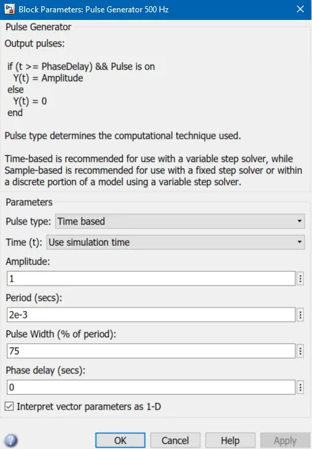
The pulse generator is used to generate the pulses which are fed to IGBT to create PWM. Hence in this model motor starts in a positive direction with a duty cycle of 75%(DC voltage of 180V). After compiling we can study the scope were graph of motor speed, armature current, and motor torque versus time.
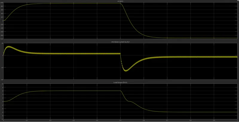
We run the above model to get the following results on the scope as shown below.
CONCLUSIONS:
So from the scope, we can see that the first half cycle motor attains the speed of 990 to 1000 RPM at a torque of 6Nm. The negative half cycle starts from 0.5 seconds where the armature voltage runs the motor in the negative direction in the second half cycle with the same values. Hence we can conclude that as the change in duty cycle is reduced below the certain standard duty cycle value then there is no shoot up in the armature current and if the change in duty cycle is above standard duty cycle, we can see there is a shoot up in armature current.
CASE STUDY 2:
Study and refer to the ‘The Four-Quadrant Chopper DC Drive (DC7) block' from Simulink and compare it with the H bridge.
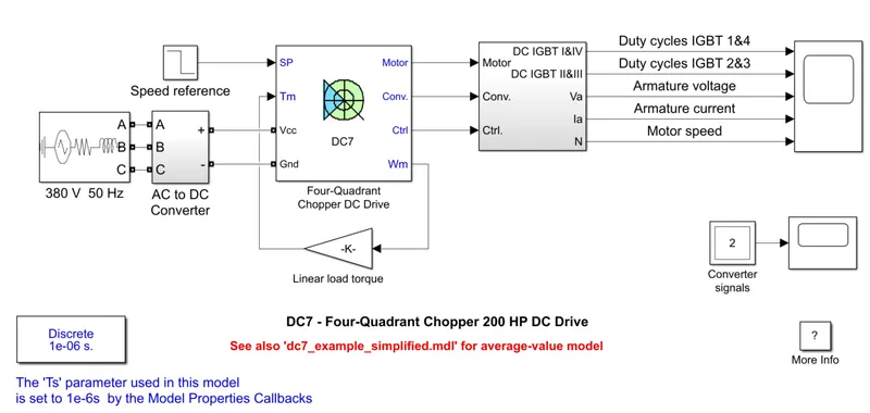
The Four-Quadrant Chopper DC Drive (DC7) block is used to control the voltage of DC current from AC to DC converter, We know that from the AC voltage supply source we are converting the AC voltage to DC voltage by using an AC-DC converter. This generated DC voltage is a variable DC voltage that can not be feed to the motor hence we use Four-Quadrant Chopper DC Drive to obtain a stable/constant voltage to the given motor application in EV.
ABOUT:
The 200 HP DC motor is separately excited with a constant 150 V DC field voltage source. The armature voltage is provided by an IGBT converter controlled by two PI regulators. The converter is fed by a 515 V DC bus obtained by rectification of a 380 V AC 50 Hz voltage source. In order to limit the DC bus voltage during dynamic braking mode, a braking chopper has been added between the diode rectifier and the DC7 block. The first regulator is a speed regulator, followed by a current regulator. The speed regulator outputs the armature current reference (in p.u.) used by the current controller in order to obtain the electromagnetic torque needed to reach the desired speed. The speed reference change rate follows acceleration and deceleration ramps in order to avoid sudden reference changes that could cause armature over-current and destabilize the system. The current regulator controls the armature current by computing the appropriate duty ratios of the 5 kHz pulses of the four IGBT devices (Pulse Width Modulation). For proper system behavior, the instantaneous pulse values of IGBT devices 1 and 4 are opposite to those of IGBT devices 2 and 3. This generates the average armature voltage needed to obtain the desired armature current. In order to limit the amplitude of the current oscillations, a smoothing inductance is placed in series with the armature circuit.
The main advantage of this drive over other drives is that it can operate in all four quadrants which are forward motoring, reverse motoring, forward regeneration, and reverse regeneration. Finally, due to the use of high switching frequency DC-DC converters, a low armature current is obtained to run the motor.
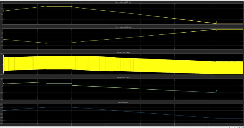
We run the above model to get the following results on the scope as shown below.
SIMULATION RESULTS:
- We can see there is positive half(Forward/Reverse motoring) and a negative half cycle(Forward/reverse regeneration) which is differentiated at the 3rd second time for armature voltage, current, and motor speed graph.
- The armature current is obtained from the average armature voltage.
- We can see that the duty cycle of the IGBT (1&4) graph is opposite to the duty cycle (2&3) graph also their pulse values are different.
- Fast response time and small ripples are obtained as the armature current follow with the current reference.
Comparing The Four-Quadrant Chopper DC Drive (DC7) block with BJT H-bridge
- In the BJT H-bridge model, the motor can be controlled by changing the pulse width of the pulse generator whereas in 4 Quadrant chopper DC drive speed reference values can be changed to control the motor.
- The 4 Quadrant chopper DC drive operates in all four modes(Forward/Reverse motoring, Forward/reverse regeneration) whereas the BJT H-bridge model operates in two modes which are forward and reverse.
- Proportional integrals(PI) controllers are used in 4 Quadrant chopper DC drive to control the speed and current whereas this is not present in the BJT H-bridge model.
- To change the direction of the motor rotation in 4 Quadrant chopper DC drives then the speed reference input is changed whereas in the BJT H-bridge model polarity is reversed to change the direction of the motor.
CASE STUDY 3:
Develop a 2 quadrant chopper in Simulink and explain its working with studied results
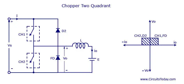
2 Quadrant chopper is a Type- C chopper. In this chopper, the output voltage is positive or zero and the output current can be either positive or negative. For this model, the input supply is 30V; load consists of 1mH inductance, 5Ω resistance, and 15V battery; and two MOSFET switches S1 and S2 and used along with two diodes as can be observed in figure. In this chopper. In this chopper when switch S1 is on current flows from source to load and when switch S2 is ON, current flows from the load through switch S2. Thus load current can be positive or negative but load voltage remains
positive. Switches S1 and S2 should not be turned on simultaneously as this would result in a short circuit of the input supply. Hence NOT gate is used for pulse generator for preventing short-circuiting.
Creating Model in Simulink:
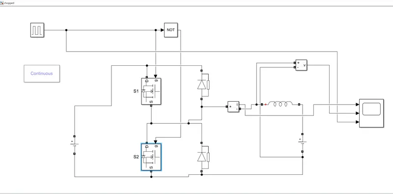
The pulse generator is fed with 0.02 second period, 10 amplitude, and pulse width of 50% and runs the above model to obtain the results.
RESULTS:
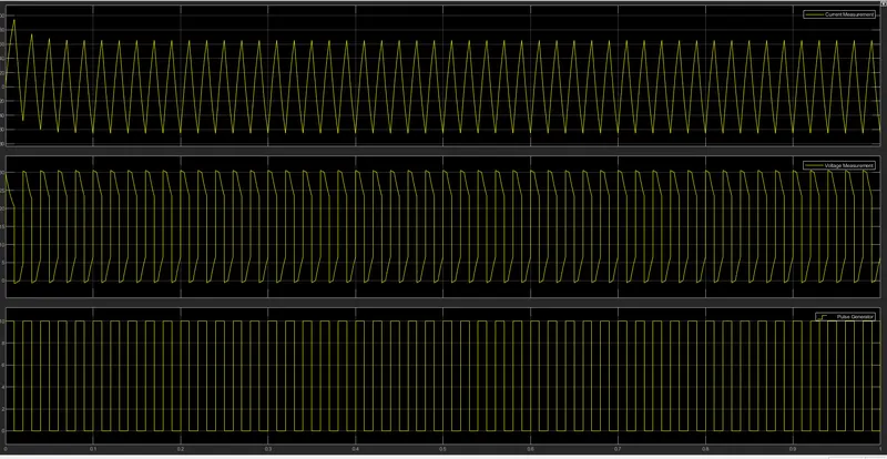
From the scope, we can see results in the graph representing current, voltage, and pulse waveform. By zooming some parts of the graph in order to study the results we get the below figure.
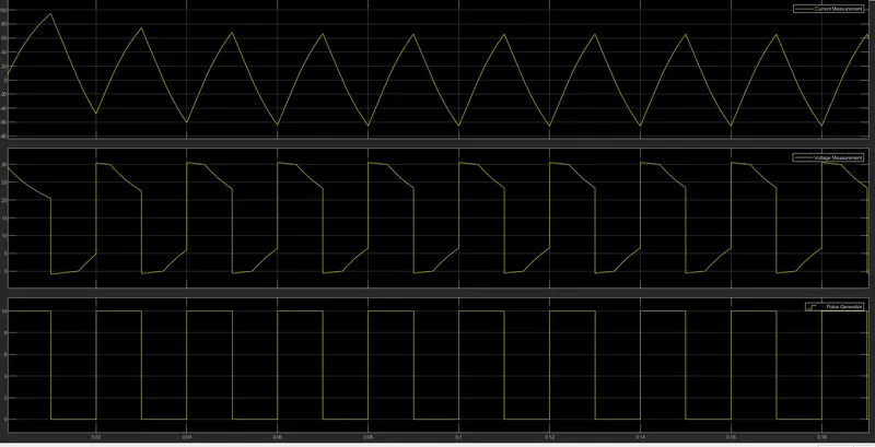
CONCLUSIONS- We get a voltage graph which is having only positive values and the current graph fluctuating both positive and negative direction which shows the above-created model in SIMULINK is 2 Quadrant chopper or Type- C chopper.
CASE STUDY 4:
Operation of BLDC(Brushless DC motor)
A Brushless DC motor does not use brushes the rotor is a permanent magnet the coil does not rotate but instead fixed in place on the stator because the coil does not move and there no need for a brush and a commutator. BLDC motor has high efficiency and controllability.
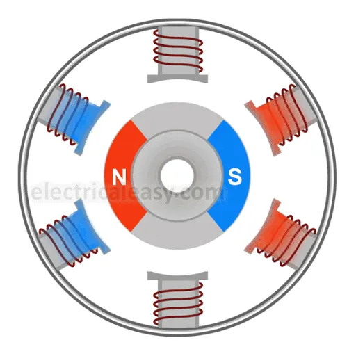
Operation of BLDC
- It consists of switches that will excite the phases of the DC motor.
- A 3 phase voltage supply should be an AC voltage supply
- When the stator coils are electrically switched by the supply source, it becomes an electromagnet and starts producing a uniform field in the air gap.
- Though the source of supply is DC, switching makes to generates an AC voltage waveform with a trapezoidal shape.
- Due to the interaction between the electromagnet stator and the permanent magnet rotor, the rotor continues to rotate.
- Considering the above figure where the motor stator is excited based on the different switching states. With the switching of the winding as high and low signals, the corresponding winding is energized as north and south pole.
- The permanent magnet rotor with north and south poles aligns with stator poles causing the motor to rotate.
- The plots of current in phase 1, Phase 2, Phase 3 of the stator should synchronize in such a way that the motor rotates in a clockwise direction or anticlockwise direction.