Week-7 Challenge: DC Motor Control
1.
A. Explain a MATLAB demo model named ‘Speed control of a DC motor using BJT H-bridge’.
H Bridge is a simple electronic circuit which enables to apply voltage to load in either direction i.e., it can run DC Motor in clockwise or anticlockwise directions. It is mostly used in robotics application to control DC Motors.
Speed control of a DC motor using BJT H-bridge
The Bipolar Junction Transistor (BJT) when used for power switching applications operates as an IGBT. When it is conducting a forward voltage Vf is developed between collector and emitter (in the range of 1 V). Therefore the IGBT block can be used to model the BJT device.
The IGBT block does not simulate the gate current controlling the BJT or IGBT. The switch is controlled by a simulink signal (1/0). Switching signal is given below the model.
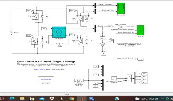
Model description:
- The DC motor uses the preset model (5 HP 24V 1750 rpm).The armature mean voltage can be varied from 0 to 240 V when the duty cycle is varied from 0 to 100%.
- The H bridge consists of four BJT/Diode pairs .Two transistors are switched simultaneously: Q1 and Q4 or Q2 and Q3.
- When Q1 & Q4 are fired a positive voltage is applied to motor and diodes D2, D3 operate as free wheeling diodes when Q1 & Q4 are switched off.
- When Q2 & Q3 are fired a negative voltage is applied to motor and diodes D1, D4 operate as free wheeling diodes when Q2 & Q3 are switched off.
- The motor starts in the positive direction with a duty cycle of 75% which is specified in the pulse generator block.
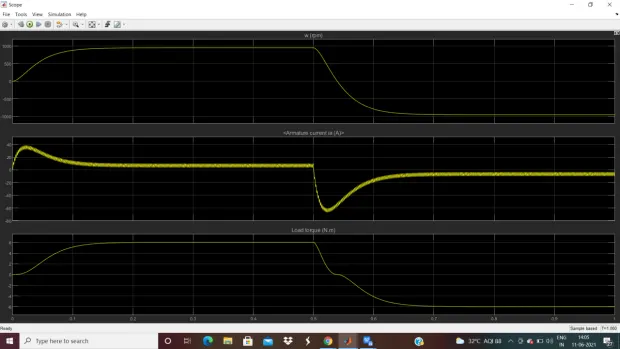
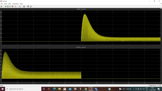
From scope we can get the motor speed, armature current and load torque and Currents shows currents flowing in BJT Q3 and diode D3.
And we can observe that for 0-0.5sec the current flows through Q3 and from 0.5- 1 sec current flows through Q3.
B.Comment on the armature current shoot-up from the scope results.
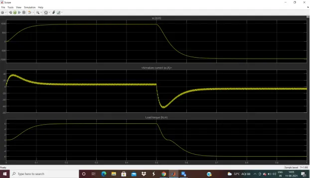
From the above scope results we can observe that simulation is done for t= 1 sec. At t= 0.5 sec. the armature voltage is suddenly reversed and the motor runs in the negative direction. Due to this we get sudden shoot up i.e., a spike armature current at starting and while reversing period.
To modify this we need to give average voltage to dc motor by changing the duty cycle in pulse generator. Pulse generation allows us to adjust the average voltage that going to the electronic device by switching on and off the power at a fast rate. Thus average voltage depends on the duty cycle.
So to reduce the armature current shoot let us change the value of duty cycle from default value.
Modification:
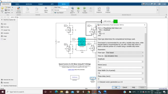
Change the value of duty cycle to 55% in the pulse generator block and observe the plot.
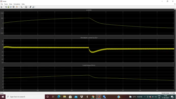
From the plot we can observe that the shoot up in armature current has been reduced when compared to the default value of duty cycle. And can be further reduced by decreasing the duty cycle.
This is how we achieve that armature current does not shoot up and it get smoothen by changing the duty cycle.
C. The Four-Quadrant Chopper DC Drive
A four quadrant chopper is a chopper which can operated in all the four quadrants.The modes of operation are Forward Motoring, Forward Braking, Reverse motoring and reverse braking. This type of chopper is also known as Class-E or Type-E chopper.
A motor drive that is capable of of operating in both direction of rotation and producing motoring and regenration is called as Four Quadrant dc drive.
The Four-Quadrant Chopper DC Drive DC7 block
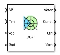
The Four-Quadrant Chopper DC Drive (DC7) block represents a four-quadrant, DC-supplied, chopper drive for DC motors. This drive features closed-loop speed control with four-quadrant operation. The speed control loop outputs the reference armature current of the machine. Using a PI current controller, the chopper duty cycle corresponding to the commanded armature current is derived.
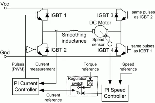
The Four-Quadrant Chopper DC Drive block uses these blocks from the Electric Drives are Speed Controller (DC),Regulation Switch,Current Controller (DC),Chopper
Working:
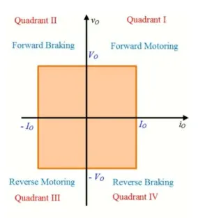
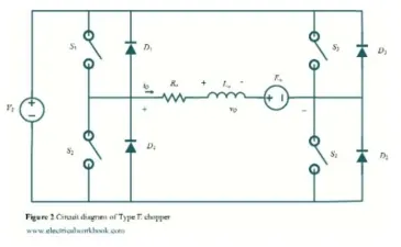
First Quadrant – Forward motoring mode
For first quadrant operation, S4 is kept on, S3 is kept off and switch S1 is operated. With S1, S4 ON, armature voltage Va = Vs and armature control Ia begins flow. Here both Va and Ia are positive giving first quadrant operation, when S1 is turned off, positive current freewheels through S4, D2 and operation gives forward motoring mode.
Second Quadrant – Forward braking mode
Here S2 is operated and S1 , S3 and S4 are kept off. With S4 on, negative current flows through La , S2, D4 and Eb. During the operation time of S2, the armature inductance stores energy. When S2 is turned off, current is fed back to source through diodes D1 , D4. As the Vs is positive and Ia is negative, it is a second quadrant operation gives forward braking mode.
Third Quadrant – Reverse motoring mode
For third quadrant operation,S1 is kept off, S2 is kept on and S3 is operated, polarity of armature back emf Eb must be reversed. With S3 is on, armature gets connected to source V. So that both Va , Ia are negative, leading to third quadrant operation. When S3 is turned off,negative current free wheels through S2,D4. In this manner only Va and Ia can be controlled in the third quadrant.
Fourth Quadrant – Reverse Braking mode
Here S4 is operated and other devices kept off, back emf Eb must have its polarity reversed as in third quadrant operation. With S4 on, positive current flows through S4,D2,La and Eb. Armature inductance La stores energy during the time S4 is on. When S4 is turned off, current is fed back to source through diodes D2, D3.Here armature voltage Va is negative, but Ia is positive, leading to the chopper drive operation in the fourth quadrant.
Comparision of 4 Quadrant Chopper DC Drive with H- bridge :
- The H bridge works in 2 modes: forward motoring, reverse motoring.
- The 4 quadrant works in 4 modes: Forward Motoring, Forward Braking, Reverse motoring and reverse braking.
- The H bridge is a 2-quadrant device will draw energy from the supply to run the load either forwards or backwards.
- A 4-quadrant device is also capable of returning energy from the load to the supply. This normally only applies to motors, where it is feasible to see the motor returning energy during braking.
- To control the motor in H-bridge, we need to change the polarity which turns into opposite direction while In 4 Quadrant drive we need to interrupt one signal under control of another.
- The 4 quadrant chopper have high switching frequency while H bridge model has low switching frequency.
- In 4 Quadrant chopper regenerative braking is possible while in H bridge it is not possible. Dynamic braking is possible in H bridge drive.
2. Two-quadrant Chopper
This chopper is also known as Type C chopper which is obtained by connecting type A and type B choppers in parallel. The two choppers should not be turned on simultaneously as the combined action my cause a short circuit in supply lines. For regenerative braking and motoring these type chopper configuration is used.
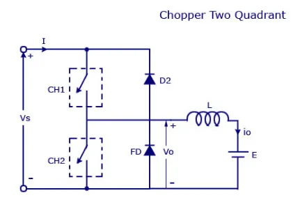
In this type of chopper we will always get a positive output voltage as the freewheeling diode FD is present across the load. When the chopper is on the freewheeling diode starts conducting and the output voltage v0 will be equal to Vs . The direction of the load current i0 will be reversed. The current i0 will be flowing towards the source and it will be positive regardless the chopper is on or the FD conducts. The load current will be negative if the chopper is on the diode D2 conducts.
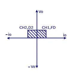
We can say the chopper and FD operate together as type-A chopper in first quadrant. In the second quadrant, the chopper and D2 will operate together as type –B chopper.
Simulink model of Two Quadrant Chopper
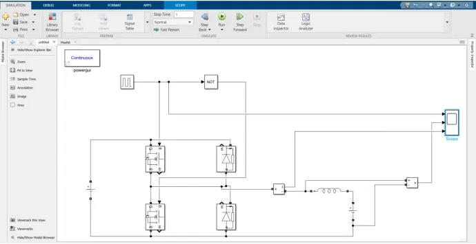
from the above fig we can observe the simulink model of Two quadrant chopper
Chopper construction:
- The chopper is designed according to the chopper circuit which consists of 2switches, free wheeling diode, diode and voltage sources.
- So for switches purpose MOSFETs , 2 diodes and voltage sources are taken from the library.
- RLC block is taken which is further converted to inductor only with default value.
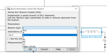
- Arrange these blocks according to the circuit.
- The Pulse generator and logical operator NOT are taken for giving gate signal to switch 1 and 2. The switch 1 gets the signal from pulse generator while s2 will get from the NOT gate.
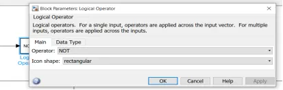
- The reason for using the NOT gate to ensure that the 2 switchesnot be turned on simultaneously as the combined action my cause a short circuit in supply lines.
- In pulse generator block the pulse width values is given as 50%. The reason for giving pulse width as 50% is that it is ON for 50% and off for 50% i.e., NOT gate ON at that time when pulse width is OFF.
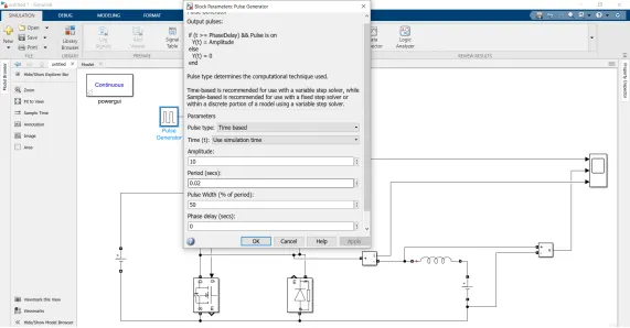
- The current and voltage measurements are observed in scope and the simulation is run for 1 sec.
Result:
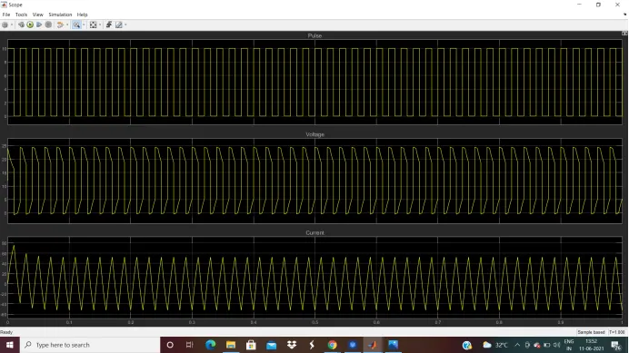
From the above we can observe that plots are of Pulse generator, current and voltage.
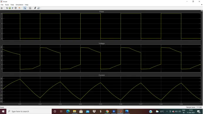
By zooming the plot From current and voltage plots we can observe that the voltage is always positive while the current is positive as well as negative or beyond zero this because of chopper is on diode D2 conducts.
3. Brush less DC motor:
Brushless DC electric motors also known as electronically commutated motors. The rotor only consists of magnets i.e. no connections, no commutator and no brushes. BLDC motors also consists of controllers, rotary encoders or a Hall sensor which detects the position of the rotor.
Construction of Brushless DC motor
In this motor, the permanent magnets attach to the rotor and the armature windings are located on the stator. The main difference between a brushed and brushless motors is the replacement of mechanical commutator with an electric switch circuit which use electrical commutation to convert electrical energy into mechanical energy.
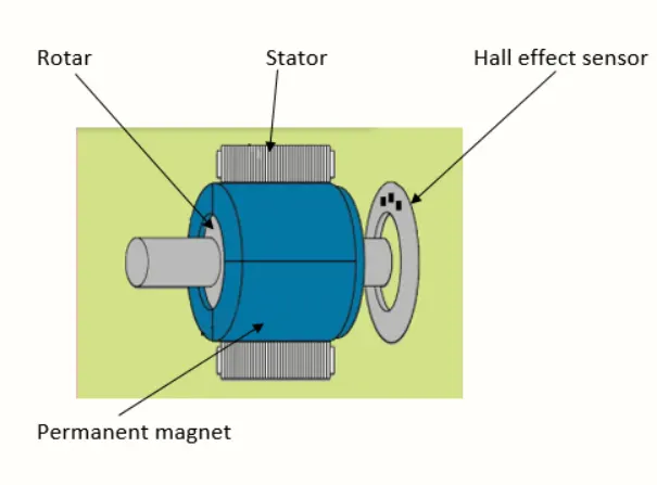
The design of a DC brushless motor can vary depending on whether it is in Out runner or Inrunner type.
Out runner
The type in which rotor rotates around the stator . This type is preferred for applications that require high torque and where high rpm isn’t a requirement.
In runner
The type in which the field magnet rotates inside the stator. This motor produces less torque than out runner, but has very high rpm.
Working Principle of Brushless DC motor
BLDC motor works on the principle similar to a Brushed DC motor. The Lorentz force law which states that whenever a current carrying conductor placed in a magnetic field it experiences a force. As a consequence of reaction force, the magnet will experience an equal and opposite force. In the BLDC motor, the current carrying conductor is stationary and the permanent magnet is moving.
When the stator coils get a supply from source, it becomes electromagnet and starts producing the uniform field in the air gap. Though the source of supply is DC, switching makes to generate an AC voltage waveform.
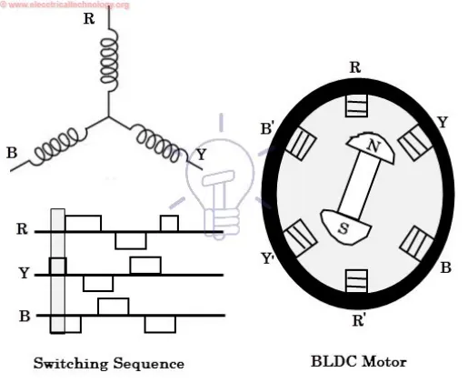
In the fig in which motor stator is excited by different switching states. With the switching of windings as High and Low signals, corresponding winding energized as North and South poles. The rotor with North and South poles align with stator poles which causes the motor to rotate. The motor produces torque because of the development of attraction forces and repulsion forces.
Hall sensors give shaft position feedback to the electronic controller unit.Based on this signal from sensor, the controller decides particular coils to energize. Hall-effect sensors generate Low and High level signals whenever rotor poles pass near to it. These signals determine the position of the shaft.
Advantages of Brushless DC motor
- Less overall maintenance due to absence of brushes
- Reduced size
- Higher speed range and lower electric noise generation.
- High efficiency and high output power
- Long life
- Low noise due to absence of brushes
Limitations of Brushless DC motor
- These motors are costly
- Requires complex drive circuitry
- Need of additional sensors