Week-7 Challenge: DC Motor Control
Explain a MATLAB demo model named ‘Speed control of a DC motor using BJT H-bridge’
The Bipolar junction Transistor(BJT) when used for power switching application, operates as an IGBT when it is conducting, a forward voltage Vf is developed between collector and emitter. Therefore, the IGBT block can be used to model the BJT device. The IGBT block does not simulate the gate current controlling the BJT or IGBT. The parameters of the DC motor are 5 HP 24V 1750rpm. The armature means voltage can be varied from 0 to 240V when the duty cycle is varied from 0 to 100%. The H-Bridge consists of four Diodes. Two transistors are switched simultaneously one is Q1 and Q4 and the other is Q2 and Q3. When Q1 and Q4 are switched on, a positive voltage is applied to the motor, and diodes D2-D3 operate as free-wheeling diodes when Q1 and Q4 are switched off. When Q2 and Q3 are switched on a negative voltage is applied to the motor and diodes D1-D4 operate as free wheeling diodes when Q2 and Q3 are switched off.
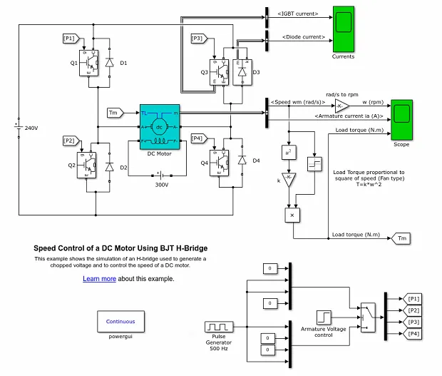
The above model consists of DC source ,DC motor block, Diodes, Pulse generator, Square block, multiply block, BJT H-bridge transistor Block, scope block, and power GUI block.
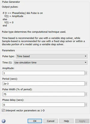
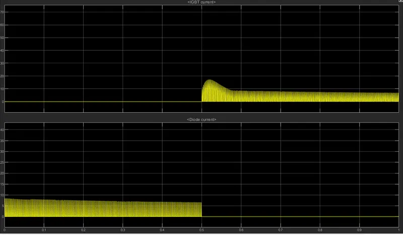
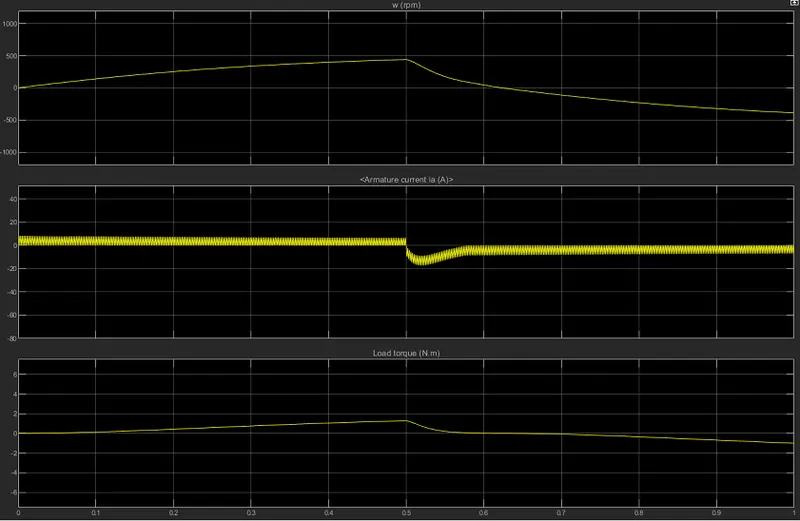
The motor starts in the positive direction with a duty cycle of 75%. The simulation time is 1sec.
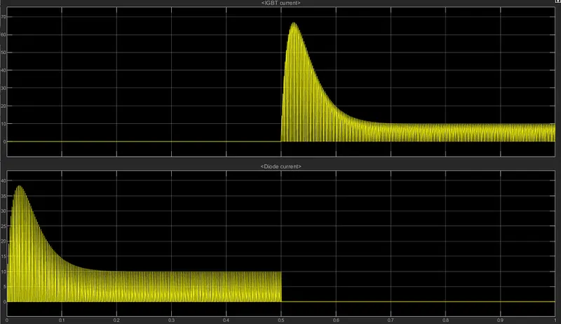
The above plot is obtained from the current scope which is connected to Q3 and it shows the output of Diode current and IGBT current of the Q3 block.
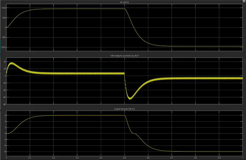
The is the output of armature current , load torque, rotation speed. Here we can see that there is a sudden fall in all these three parameters this is due to the duty cycle percentage is higher.
Then the duty cycle is changed to 50% and the stimulation time is the same.
The above plot is obtained from the current scope which is connected to Q3 and it shows the output of Diode current and IGBT current of the Q3 block.
The is the output of armature current , load torque, rotation speed , here we can see the sudden fall is reduced due to the reduction of duty cycle to 50%.
Then the duty cycle is changed to 25% and the stimulation time is the same.
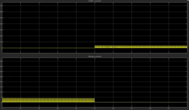
The above plot is obtained from the current scope which is connected to Q3 and it shows the output of Diode current and IGBT current of the Q3 block.
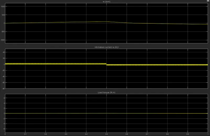
The is the output of armature current , load torque, rotation speed , here we can see that there no sudden fall when we changed the duty cycle to 25%.
|
FOUR QUADRANT CHOPPER |
BJT H-BRIDGE |
|
From the name itself, we can say that it operates in four quadrants |
BJT H-Bridge can only operate in Two quadrants |
|
Four quadrants are Forward motoring, reverse motoring, forward braking, reverse braking |
Two quadrants are Forward motoring, Reverse motoring. |
|
Regenerative braking is possible |
Regenerative braking is not possible |
|
This is used in automobile application |
This is used in robotics application |
|
There is no armature current shoot up |
Their armature current shoot up |
|
It has a high switching frequency |
It has a low switching frequency |
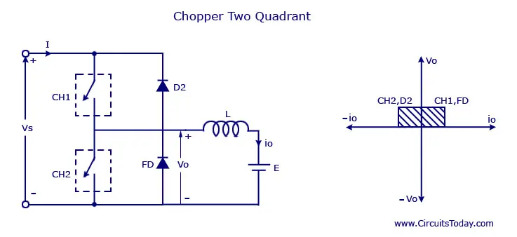
Two quadrant chopper:
This is the type of chopper where the average voltage will be always positive but the average load current will be positive or negative. The two switches CH1 and CH2 should not be turned on simultaneously as it will lead to a short circuit. The output voltage will be positive always as the diode FD present across the load. When CH1 is on condition the current flows from source to load and the indicator stores the energy and after CH1 is turned off the diode starts conduction voltage which means output voltage will be equal to source voltage. Then the direction of current is reversed and it flows towards the source and the load current will be negative when CH2 is turned on and then the current passes through the diode D2 which completes its path.
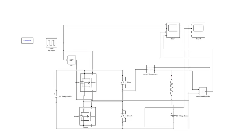
The below image is the model of the two-quadrant chopper model which is developed in Simulink. This model has a pulse generator, NOT gate, MOSFET block, diode, DC voltage source block, current measurement block, voltage measurement block, Series RLC block and scope block, power GUI block.
The main DC voltage source is 24v and the other which is connected to series RLC is a 12V source. The current measurement and voltage measurement block are connected to the two-quadrant chopper and it is connected to the scope. The NOT Gate is connected to MOSFET to ignore short circuits and to that do not allow to conduct both MOSFET at the same time.
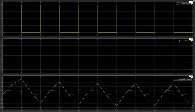
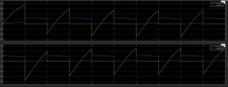
This the plot which is obtained from the scope block and it gives the output of the pulse generator, and the current measured and the voltage measured The amplitude value is 20, and the duty cycle is 50% and the stimulation time is 0.1sec.
Brushless DC Motor:
Brushless DC motor consists of two or more permanent magnets which are present in the rotor that generates a magnetic field that reacts with current flowing in winding which produces torque. All the electrical energy produces is then converted to mechanical energy. Brushless Dc motor has a cooling system so the heat produced by the motor is low so there is less loss of energy in form of heat
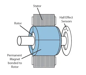
Working of Brushless DC Motor:
The brushless DC motor consists of the stator which is made up of armature winding where current passes through it and the rotor which is nothing but a permanent magnet which is the rotating part in this motor. So this motor is constructed in two ways one is in such a way that a permanent magnet is placed in the center and surrounded by many armature winded conductor which means the rotor is placed in the center of all stator and another way is all stator is placed in the center and the rotor rotates over the stator.
From the above picture, we can see that how both stator and rotor are placed and how armature winding is done. Hall sensor places the main role in this motor. If a positive current passed through the stator it will get magnetized and then it will attract the poles of the permanent magnet and then repel it. The work of the Hall sensor which is known as the electronic commutator is to send the required positive and negative current to the stator of armature windings so then only it will get excited and attract the permanent motor and makes it rotate faster so this passage of positive and negative electrical current is done by hall sensor.In the above image, we can see the graph where it indicates the working of the hall sensor while the rotor is rotating and also says about current passed to armature windings.