Project
AIM
To conduct a system-level analysis in BAJA ATV
MODEL 1-Baja ATV without a dashboard, without a lookup table
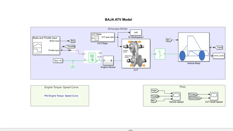
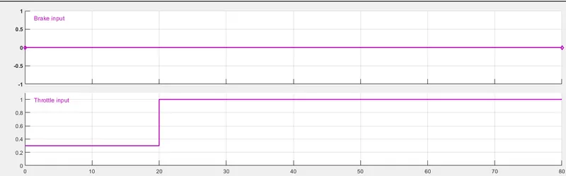
SIGNAL BUILDER -in this particular model we have used this signal builder block to produce our prime inputs such as THROTTLE and BRAKE. verterThrottle input is generally given to the generic engine [T port] simscape block using converter snd we have also used From to block to take this specific input for further process such as plotting similarly Brake input is given to FromTO block to use that values in other subsystems such as vehicle body and it can be used in plotting using GOTO block
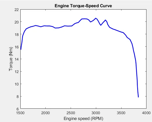
GENERIC ENGINE-This block can be used as both SI and CI engine. Generally, SAE Baja uses a 310cc SI engine with its own standard. This Engine is our source of velocity where it can be produced by giving various parameters such as speed vector, torque vector, and idle RPM. The throttle input signal T lies between zero and one and specifies the torque demanded from the engine as a fraction of the maximum possible torque. These complex varying inputs can be given by point Extraction method in a Plot, our engine maximum rpm is 3800 and the speed and torque vector is extracted by Grabit method and these points are extracted and saved in Matlab workspace as a matrix. Then we can just mention the name of the matrix in our engine to load the data of the speed vector and torque vector. The initial velocity is defined as 1600 RPM in the generic engine block
ENGINE SENSOR SUBSYSTEM-
BLOCKS USED
- Ideal Rotational Motion Sensor
- scope
- Rotational Motion sensor
- PS Terminator
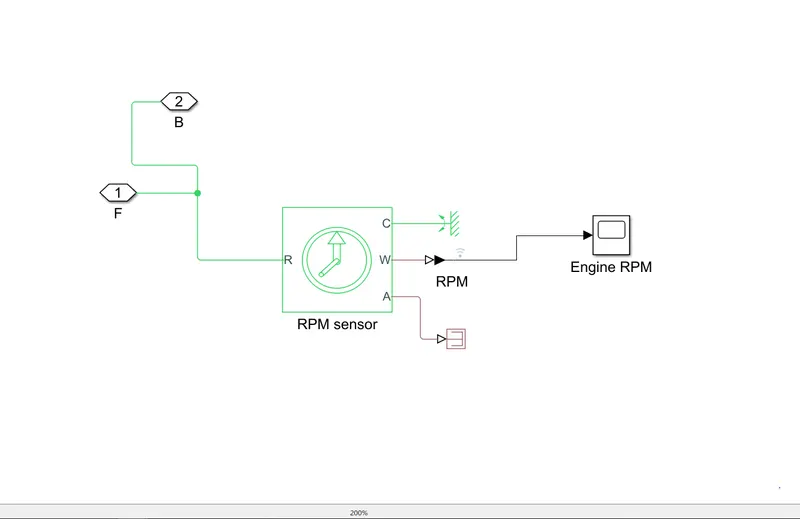
This subsystem generally consists Rotational Motion sensor block which is used to sense the angular velocity of the crank from the engine. This block has a c and R port which are mechanical rotational conserving ports that connect the block to the nodes whose motion is being monitored. port A and W are physical signal output ports for velocity and angular displacement, respectively. The engine Rpm is monitored by the block using the scope. F and B ports are connected using PMC port. C port is connected to the rotational reference.
Engine Torque input is generally is extracted from the plot. This method is generally known as the Grabit method where we can extract the values from the plot and stored them in our workspace. These torque values are given as input in our model.
From the below plot we can extract the points and stored them in the workspace.
ENGINE RPM OUTPUT
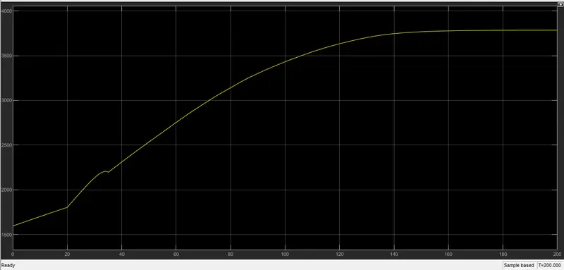
MAX RPM=3800
CVT SUBSYSTEM
BLOCKS USED
- CVT block
- Ideal Rotational Motion Sensor
- scope
- PMC
- inertia block
- rotational reference
- goto
- PS Terminator
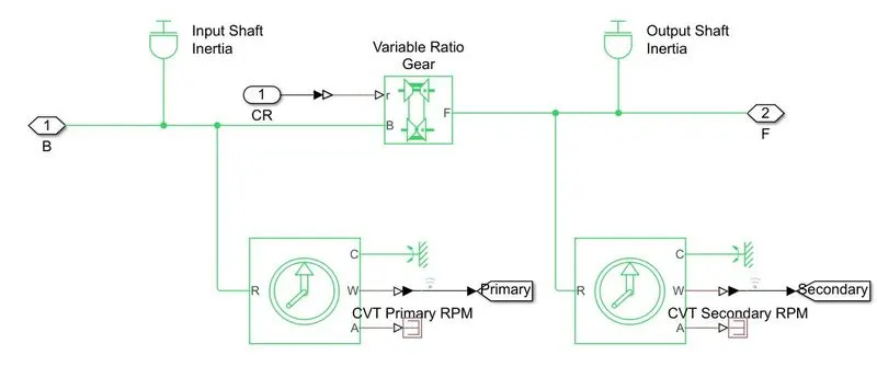
CVT is generally known as continuously variable transmission which consists of two pullies one is PRIMARY PULLY which is connected to the engine shaft and the other one is SECONDARY PULLY which is generally connected to the gearbox. Nowadays CVT is commonly used in commercial vehicles like Hyundai i20 etc. In Tuf muddy surface and in While Off-roading CVT gives the best performance. That is the reason Baja Buggies Prefer CVT for the races. This block generally Represents a variable ratio gearbox such as implemented by mechanical belt CVT, electric, or hydraulic transmissions. The physical signal input r defines the ratio of input to output angular shaft velocities.
- Ideal Rotational Motion Sensor -monitors both input snd output shaft's RPM so we can get the input speed as well as output speed. These values are carried through From to block -Goto block
- PS Terminator terminates other unwanted physical outputs from the Ideal Rotational Motion Sensor.
SIMPLE GEAR
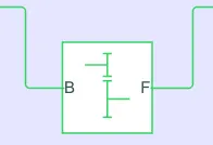
- This is a Reduction gear block, generally, the Baja team uses this gearbox to achieve high torque at low RPM.
- gear Ratio should be provided for our requirement.
VEHICLE BODY SUBSYSTEM
Blocks used
- Vehicle body
- Double brake shoe
- Tire
- PS terminator
- Rotation Free block
- inertia Block
- input blocks
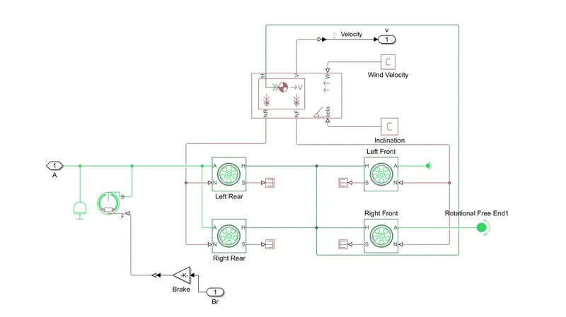
Vehicle Body block is a very useful block. It generally Represents a two-axle vehicle body in longitudinal motion. We can provide body mass, aerodynamic drag, inclination in the road, and distribution of weight between axles. The vehicle can have the same or a different number of wheels on each axle. Optionally include pitch and suspension dynamics or additional variable mass and inertia. The vehicle does not move vertically relative to the ground. The inputs like the inclination and the wind velocity depend on the road condition and vehicle performance.
Brakes; In our model double shoe brake is used in the rear axle and the front axle is set to free rotation using rotational free block which means it is not power-driven so no brake is also used in the front axle
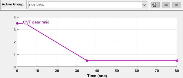
signal builder is block is used here to provide the input for our CVT ie varying ratio
Results
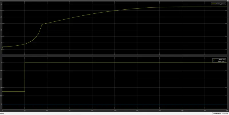
- the velocity of the vehicle WRT to our condition
- Throttle input increases rapidly which does not actually happen in real-time accelerating a vehicle.
- computer-generated signals.
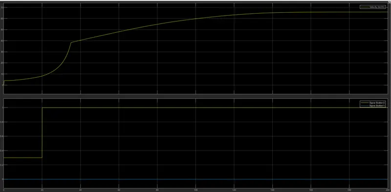
CVT OUTPUT
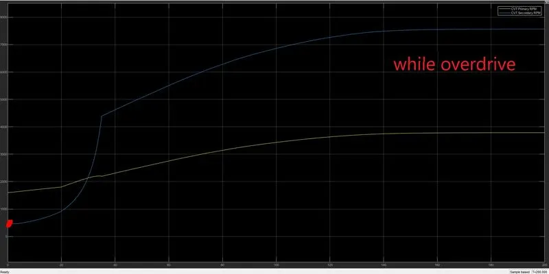
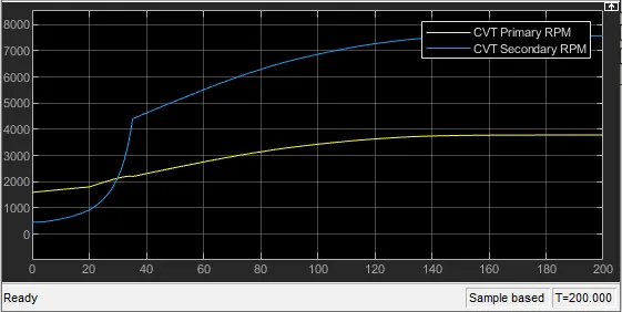
At the initial condition of lower RPM, secondary pully revolves lesser than primary pulley. At higher rpm, from engine output, the secondary pully revolver higher than the primary this condition is generally known as OVERDRIVE.
Model 2- With Dashboard and without look table
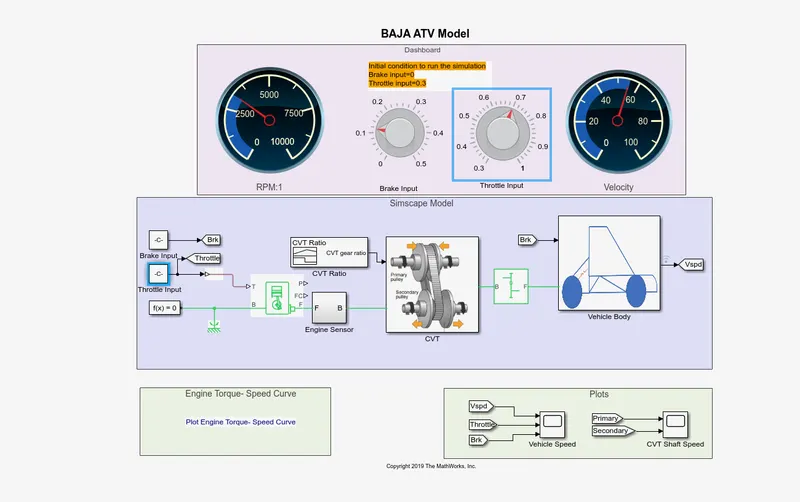
- In this model, we just set a dashboard which a speedometer and an RPM block which is generally controlled by the two regulators
- In the previous model, we use signal builder to provide the throttle and brake input. which is not relevant in real-time application.
- so we have set this dashboard setup, where we can provide input by adjusting the regulator block.
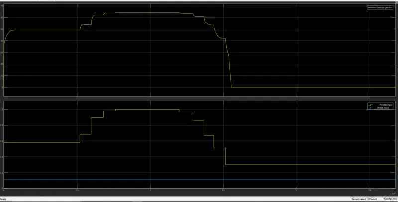
- when the throttle input is increased rpm and speed increases respectively.
- This method is more efficient and the Output data is more accurate comparatively.
CVT SHAFT SPEED
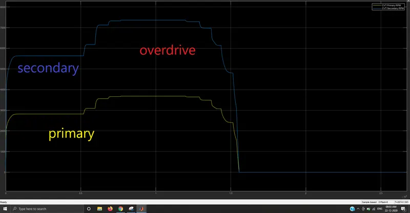
- Here we can see clearly that the secondary and primary pullies rpm where no brake is applied and the vehicle is continuously in overdrive.
- Rest of the model is similar to the basic model.
Vehicle speed
MODEL3- WITH DASHBOARD AND WITH LOOKUP TABLE[more efficient]
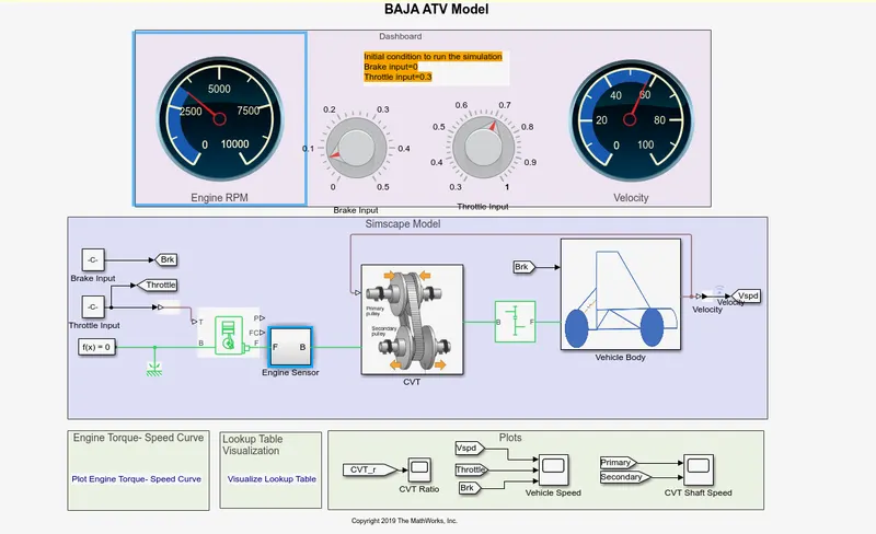
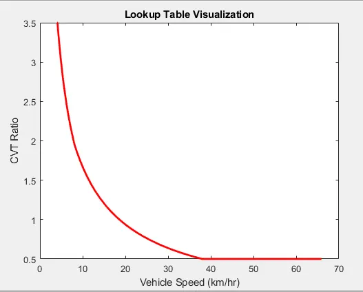
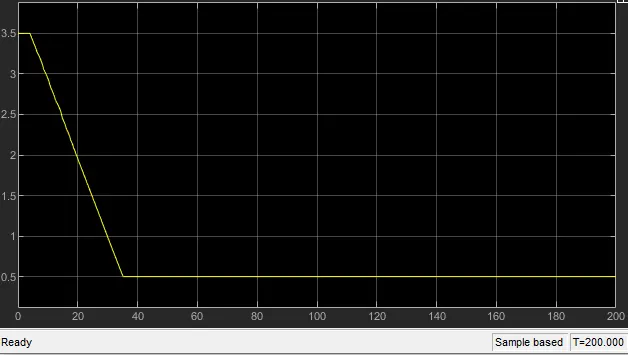
- Generally, the CVT ratio varies with respect to the engines RPM
- In this model, we have used a lookup Table concept where the CVT ratio differs
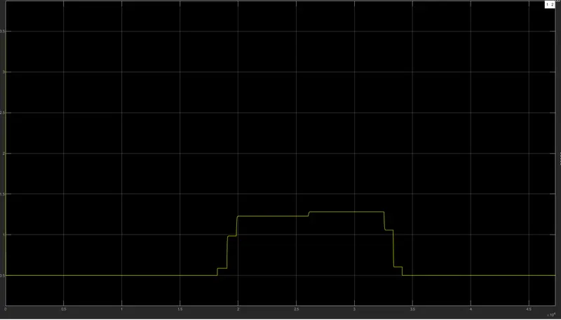
- In the previous model, we have provided the CVT ratio using signal builder which is not relevant to real-time application because CVT ratios vary with respect to engine rpm, so we have used a lookup table script which generally takes the feedback signal from the vspd[vehicles velocity]
- so we can achieve more accurate CVT ratios at dynamic conditions.
LOOKUP TABLE
CVT SHAFT SPEED
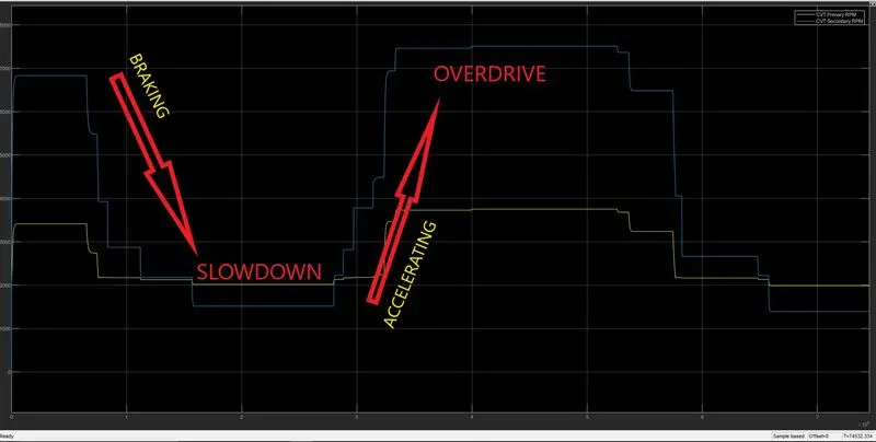
- While braking primary pulley rpm is more than secondary pully and while accelerating
- in this model, we get more accurate results, which is similar to the real-time application.
CVT RATIO
Vehicle speed
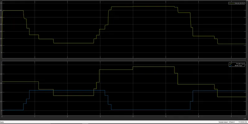
MODEL-WITH LOOKUP table without dashboard
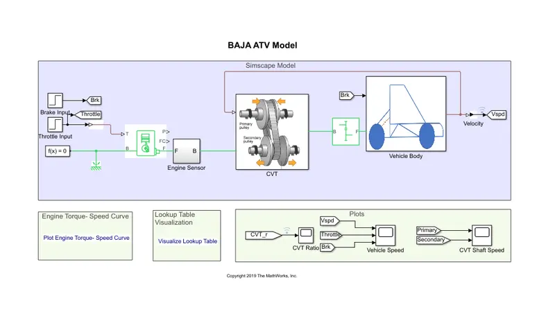
- In this model, we didn't use the dashboard block.
- That is the main difference.in this particular model, we have used this signal builder block to produce our prime inputs such as THROTTLE and BRAKE. verterThrottle input is generally given to the generic engine [T port] simscape block using converter snd we have also used From to block to take this specific input for further process such as plotting similarly Brake input is given to FromTO block to use that values in other subsystems such as vehicle body and it can be used in plotting using GOTO block.
- Rest of the model is similar to the above mentioned block
cvt ratio
CVT RATIO
vehicle speed