Week -2
AIM
- To make a simulink model of simple door bell using solenoid
- To make a simple cooling system model in simulink using Thermister
DOOR BELL
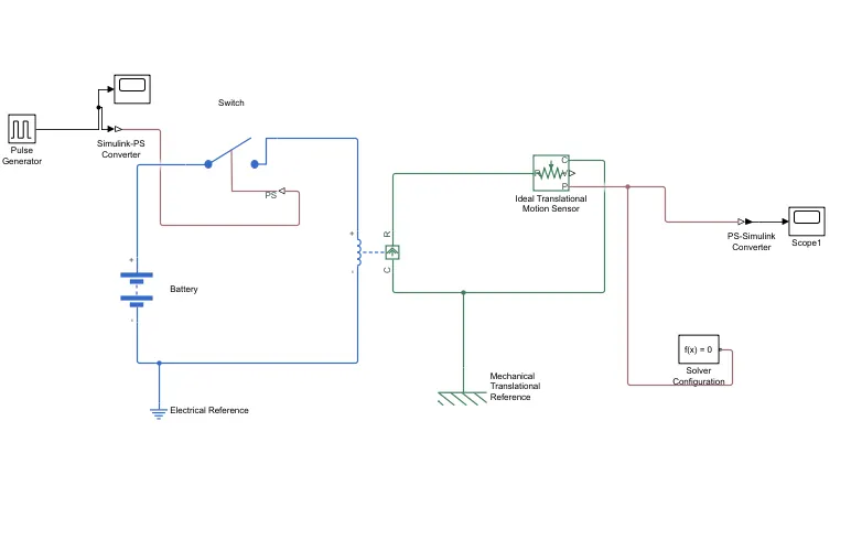
Blocks required
- Solenoid
- Battery
- switch
- pulse generator
- scope
- signal converters
- references
- translational motion sensor
Procedure
- Initially we have to connect the electrical circuits
- The neagtive terminal of the battery is connected with negative side of the solenoid
- solenoid is a eloctomechanical device which induce a electro magnetic effect on a piece of rod which winded with coils
- positive terminal of the battery is connected to the switch ,which close/break the circuit
note: There are lot of switch models available in simulink so be aware of the required model of the respective project
- elecrical earth reference is connected with neagtive side
- As per the challenge we need to close the circuit for two seconds ,for that we need to provide input in such ways
- Pulse generator is used to build signal for our requirement . amplitude of the pulse generator remains same as 1eith phase delay of 2 seconds
- total period taken by the pulse generator is 4 seconds and pulse width of 50
- To connect pulse generator with switch we have to use simulink to physical converter
input
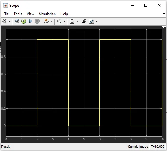
- this is how the input has been produced,to view this we should connect scope block
- now coming to the mechanical part we need an ideal translational motion sensor to monitor the plnger movement of the solenoid
- ideal translational motion sensor is block which sense the translational motion of any mechanical component,the outputs from ideal translational motion sensor are velocity and position V,P respectively
- R-R ports are connected from solenoid to ideal translational motion sensor and c port is connected to mechanical translational reference
- solver block is connected to avoid error.
- output is viewed by connecting physical simulink converter to scope
Output
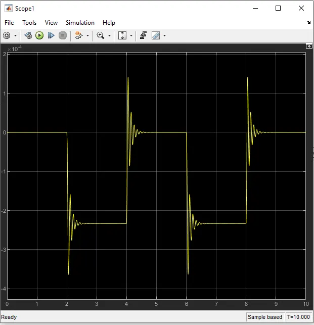
- here we can see that the after 2 seconds the plunger moves from it neutral pos and vibrated to rings the bell as per our concept.
Thermister cooling system MODEL
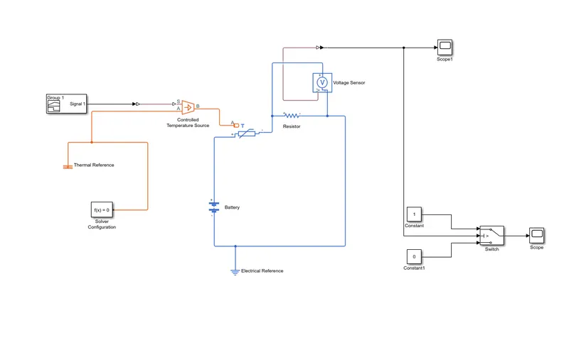
Blocks used
- NTC thermister
- signal builder
- controlled temperature source
- voltage sensor(voltmeter)
- resistor
- battery
- references
- logic switch
- constant blocks
- scope
- solver
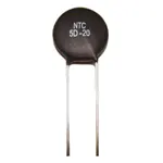
NTC THERMISTER generally reduce or decrease their resistive value as the operating temperature around them increases. Generally, NTC thermistors are the most commonly used type of temperature sensors as they can be used in virtually any type of equipment where temperature plays a role.
Procedure
- Our aim is to turn on our fan if the system temperature is above 25 degree celcius and turn off if the temp is below 25 degree celcius using a thermister
- in thermister configuration temperature referance and begining temperature value is 293k
- gennerally thermister is temperature sense resistor
- Initially we have to connect the electrical circuits
- we have connect the thermister with battery source ,so +ve terminal of the battery is connected with +ve side of the thermister and -ve side of the thermistor is conncted with +ve terminal of the resistor
- electrical earth ref is connected to -ve terminal of the battery
- voltmeter should be connected in parralel to circuit
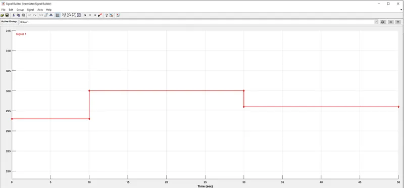
- we know at what time what temperature should be given ,so we need to give inputs such in signal builder
- in signal builder x axis is for time and y axis is set as temperature range for our project .you can click on the points or drag the points to define the input [time,temperature] specifically
condition;
Runtime-50 sec
- 0-10 sec[20 deg cel]
- 10-30 sec[27 deg cel]
- 30-50 sec[23 deg cel]
signal builder input
- then the temprrature sourse provide the the temperature to the thermister and thermister starts to behave wrt temperature change in time
- hence voltage across thecircuit also chnages and its is moniyored by the voltmeter
voltmeter output
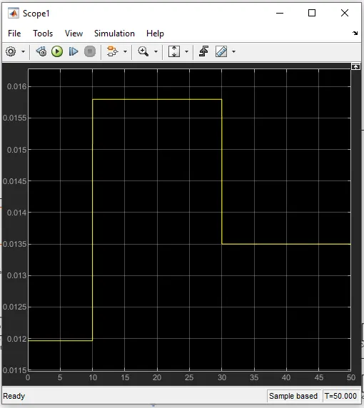
- the voltage also changes wrt our input temperature because of the thermistor
- our aim is to turn on/off the fan according to this inputs
- we need to get a logic switch from the library which has three ports
- middle port gets the input from volatge sensor
- top port is with constant 1 [ON ]
- bottom port is with contsant 0[OFF]
- thershold should be set as per the logic (when the temp is getting increased )
- above fig we can get the value of threshold {above 25 deg cel,0.0145}
- so, logic is set,when u2>[0.0145] constant 1 applied and the switch is turned on until this logic fails
- after fan cools the system and temp drops below 25 deg cell ,contsant 0 applied to turn off.
OUTPUT of the SWITCH which applies a simple logic
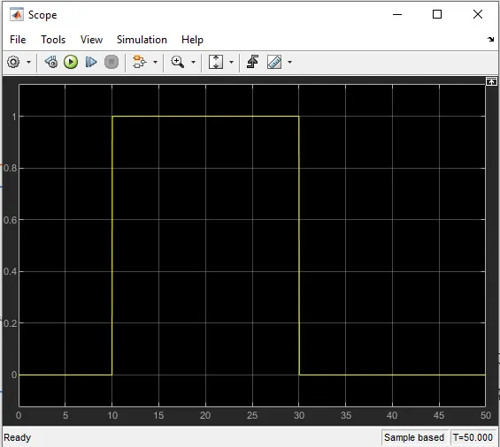
- hence the fan is turned on when the temp goes above 25 deg celsius and after the fan cools downthe system fan is turned off
- this is very helpfull automatic function and it can applied in various applications too
conlclusion
Thus we have created a simple and very helpfull model using the simulink blocksfor both the objective