Week-7 Challenge: DC Motor Control
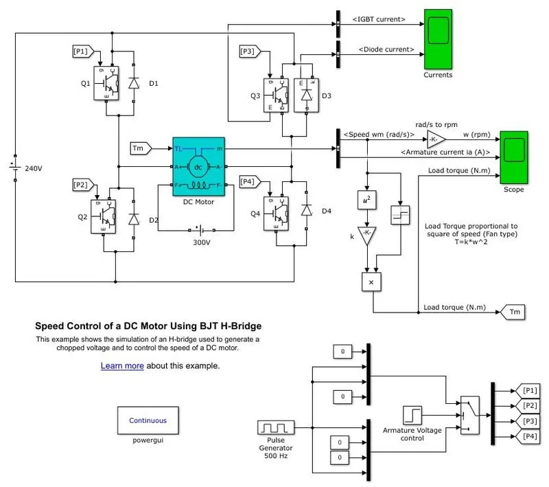
1. A. Explain a MATLAB demo model named ‘Speed control of a DC motor using BJT H-bridge’.
Explaination:
The Bipolar Junction Transistor (BJT) when used for power switching applications, operates as an IGBT. When it is conducting (BJT operating in the saturated region), a forward voltage Vf is developed between collector and emitter (in the range of 1 V). Therefore, the IGBT block can be used to model the BJT device.
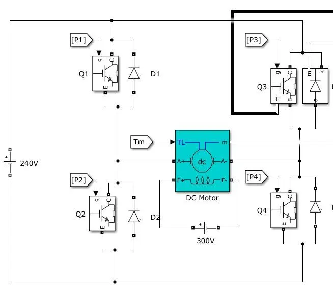
The IGBT block does not simulate the gate current controlling the BJT or IGBT. The switch is controlled by a Simulink signal (1/0). The DC motor uses the preset model (5 HP 240V 1750 rpm). It simulates a fan type load (where Load torque is proportional to square of speed). The armature mean voltage can be varied from 0 to 240 V when the duty cycle (specified in the Pulse Generator block) is varied from 0 to 100%.
The H-bridge consists of four BJT/Diode pairs (BJT simulated by IGBT models). Two transistors are switched simultaneously: Q1 and Q4 or Q2 and Q3. When Q1 and Q4 are fired, a positive voltage is applied to the motor and diodes D2-D3 operate as free-wheeling diodes when Q1 and Q4 are switched off. When Q2 and Q3 are fired, a negative voltage is applied to the motor and diodes D1-D4 operate as free-wheeling diodes when Q2 and Q3 are switched off.
B. Comment on the armature current shoot-up from the scope results.
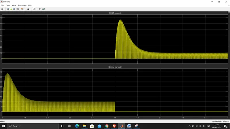
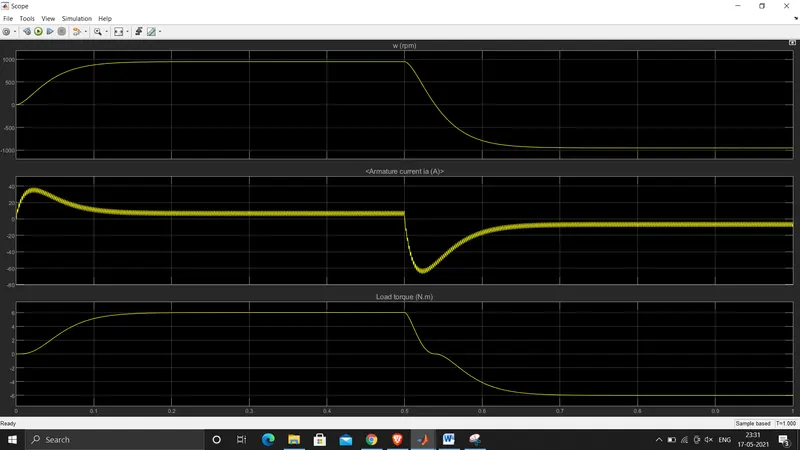
The motor starts in the positive direction with a duty cycle of 75% (mean DC voltage of 180V). At t= 0.5 sec., the armature voltage is suddenly reversed and the motor runs in the negative direction.
'Scope' shows motor speed, armature current and load torque and 'Currents' shows currents flowing in BJT Q3 and diode D3.
For a DC motor we can give the terminal voltage as
V= Eb + IaRa …..(1)
Where, Eb = back emf, Ia=armature current, Ra= armature resistance
And we know back emf in DC motor is proportional to Speed W
Eb = K W, K=DC motor constant
At starting speed W = zero, therefore Back Emf Eb =0
Therefore, from equation 1
Terminal voltage V = Ia Ra…..(2)
==> Ia = V/Ra ….(3)
as Ra value is very small in order, the Ia magnitude will be high at the starting once the motor picks up speed the Back EMF will come into picture which in turn decrease the Armature current
we can reduce this starting inrush current by reducing the Voltage at the Terminal Eq(3)of Dc motor during starting. i.e, we can reduce the duty cycle to control the inrush current during starting
C. Refer to the help section of ‘The Four-Quadrant Chopper DC Drive (DC7) block’. Compare it with the H-bridge model.
| H-bridge model drive | The Four-Quadrant Chopper DC Drive (DC7) |
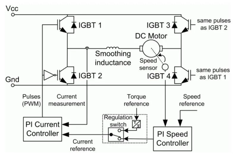
| This is a open loop control drive | drive features closed-loop speed control with four-quadrant operation |
| as there is no close loop feedack auto regulating of duty cycle to control the armature current is not possible | using armature current as a close loop, drive can control the inrush current by controlling the duty cycle |
| operates in two quadrant, forwars motoring and forward generation | operate in all four quadrants (forward motoring, reverse regeneration, reverse motoring, and forward regeneration) |
| two switching device is required, less complicated | four switching devices are required, which increases thecomplexity of the drive system. |
 |
 |
2. Develop a 2-quadrant chopper using simulink & explain the working of the same with the relevant results. (Refer to article - Multiquadrant operation of motor )
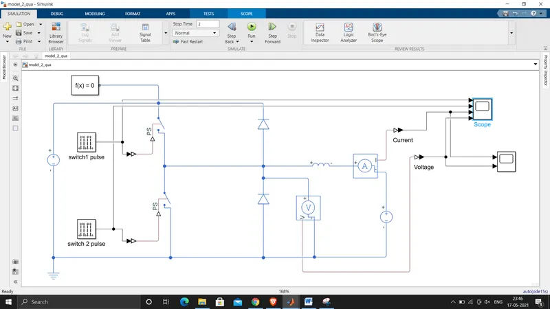
A Simulink model for 2-quadrant chopper is modelled using simple control switch and voltage source, also simulink file attached.
Plot:
working:
in cycle 1:
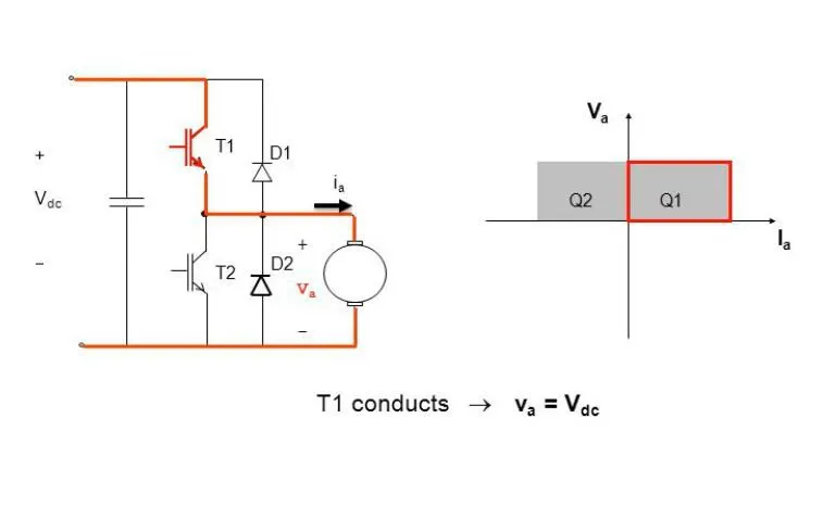
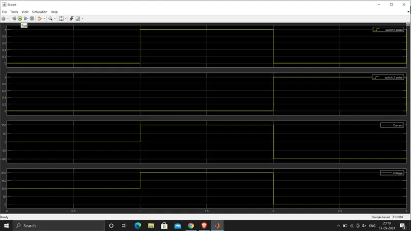
the switch T1 will close and T2 remain open, (note1, at any given time T1 and T2 both should not be closed), during this the source Vdc will be applied accross the motor, Va will be equal to Vdc, the motor will operate in 1st quadrant, that is in motoring action.
in Cycle 2:
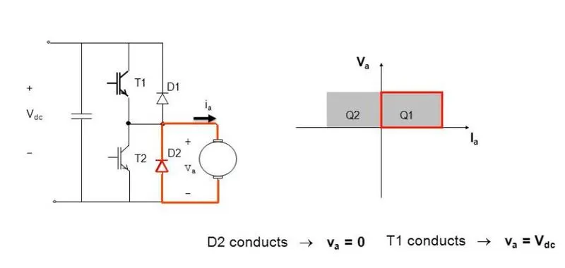
the T1 and T2 switch will be in off condition, votage accross the motor will be zero, due to Diode D2 the freewhelling of stored (energy stored in inductor)Current Ia take place, during this the motor still will be in quadrant 1, and motor will be in coasting condition
Cycle 3:
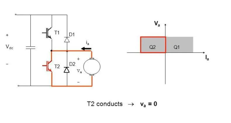
switch T1 will be off and switch T2 will be ON, during this condition the motor will be operating in breaking mode( in case of EV we can consider this as breaking)
Cycle 4:
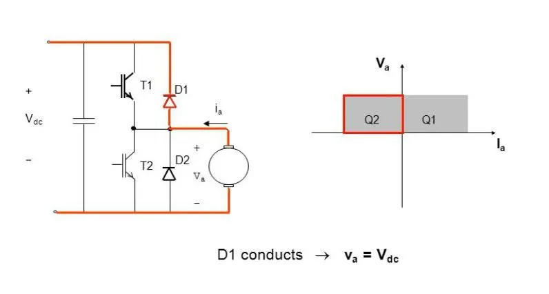
in this condition againn both the switch T1 and T2 will be open, during this condition the back emf of the motor will be equal or more than supply voltage Vdc, this mode is also breaking mode, insteaded of lossing the energy in freewheeling it can be stored, in case of EV this will be called as regenerative breaking
3. Explain in a brief about operation of BLDC motor.
Explaination:
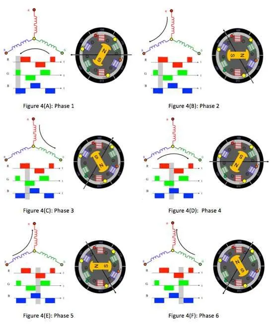
Stator windings of a BLDC motor are connected to a control circuit (an integrated switching circuit or inverter circuit). The control circuit energizes proper winding at the proper time, in a pattern which rotates around the stator. Permanent magnets on the rotor try to align with the energized electromagnets of the stator, and as soon as it aligns, the next electromagnets are energized. Thus, the rotor keeps running
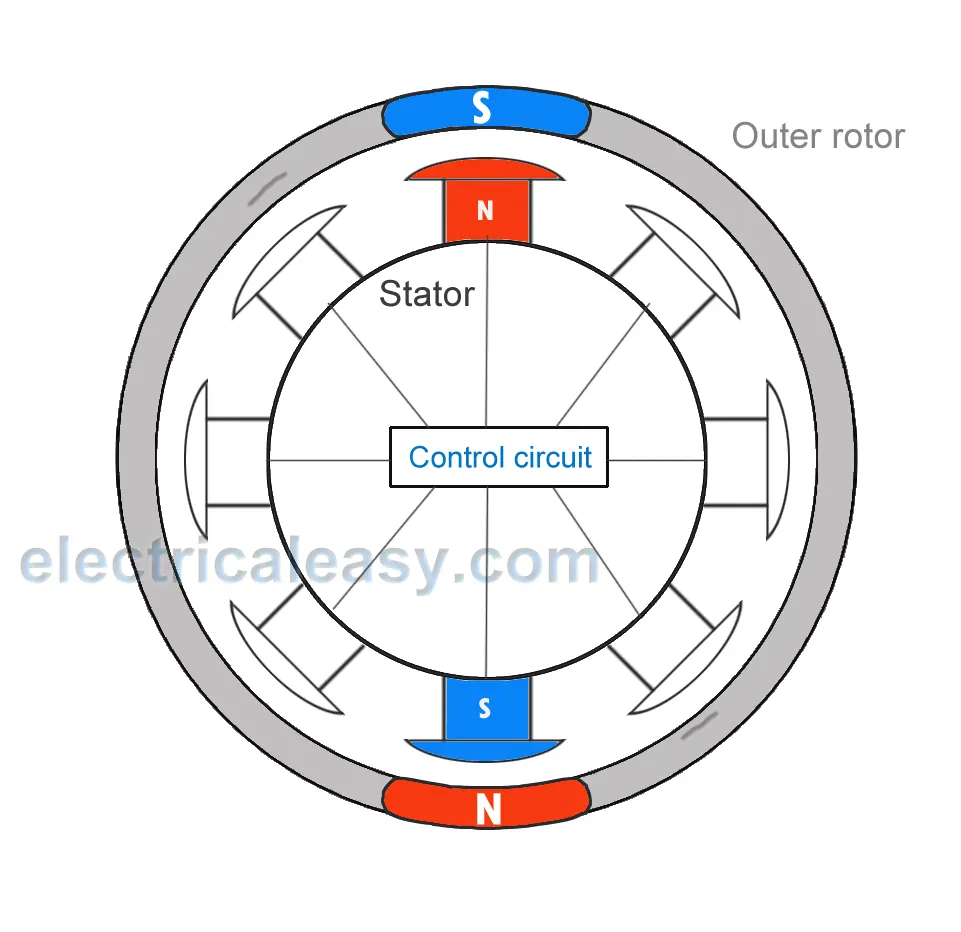
This torque is at its maximum when the rotor starts to move, but it reduces as the two fields align to each other. Thus, to preserve the torque or to build up the rotation, the magnetic field generated by stator should keep switching. To catch up with the field generated by the stator, the rotor will keep rotating.