Week-6 Challenge: EV Drivetrain
1. Which types of power converter circuits are employed in electric and hybrid electric vehicle?
Power Convertor types can be classified into 4 types:
1) AC to DC Convertor : ( Rectifier)
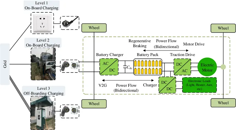
AC/DC converter which supplies electric power from a commercial power system (AC) to an onboard battery (DC), it convert Alternating 1 phase 230V/110V 50/60Hz (untility voltage depends on county grid) to Pure DC Voltage of required level to charge the battery, in case of hybride Vehical if a 3Phase generator is available then a 3phase Rectifier circuit can also be used to convert the supply power from AC generator to DC power to store in the battery.
2) DC to AC Convertor : (Invertor)
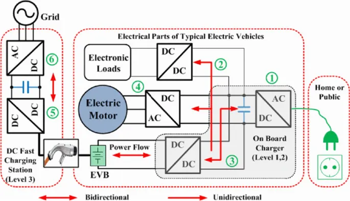
inverter is an electrical device that converts electricity derived from a DC (Direct Current) source to AC (Alternating Current) of the type that can be used to drive the AC motor,
3) DC to Dc Convertor : (Chopper/Booster Circuit)
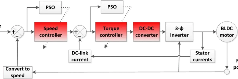
high power DC/DC converters is necessary for EV power supply system. The power of the DC/DC converter depends on the characteristics of the vehicle such as top speed, acceleration time, using DC to DC convertor voltage accross the DC traction motor (BLDC) can be changed match with vehical torque characteristic.
Also Can be used to drop the Battery Volatge level to match with other auxillaries like Lamp, Heater, and other load in EV
4) AC to AC Convertor : (Veriable Frequency Drive)
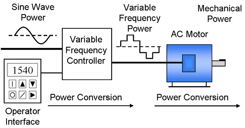
variable frequency drives (VFDs) provide the adjustable motor speed that can actually reduce energy consumption by adjusting the frequency and voltage of the AC supply .This means that at light loads the inverter can reduce voltage such that magnetic losses are reduced and efficiency is maximized
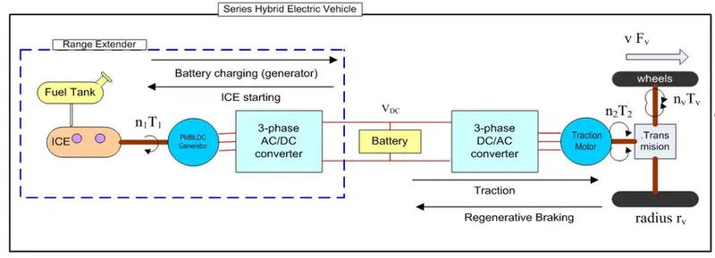
2. An Electric Vehicle's powertrain with 72V battery pack in shown in the diagram below. The duty ratio for acceleration operation is 'd1' and for the braking operation the duty ratio is 'd2'.
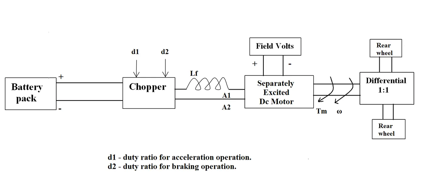
The other parameters of the electric vehicle is given below,
Motor and Controller Parameters:
Rated Armature voltage= 72 V
Rated armature current= 400 A
Ra= 0.5Ω, KΦ= 0.7 Volt second
Chopper Switching frequency= 400 Hz
The vehicle speed-torque characteristics are given by the below equation

What is EV steady state speed if duty cycle is 70%?
Solution:
as duty cycle is 70% => motor terminal voltage will be = 0.7* 72 = 50.4V
For DC motor we can give Torque equation:
`T(m) = V k/(Ra) - k^2/(Ra) w`
`T(m) = 50.4 ( 0.7/0.5) - (0.7^2/0.5)w`
`T(m) = 70.56 - 0.98 w`
also it is given Vehical Torque Characteristic is `Tv =24.7 +(0.0051) w^2`
at normal operation the motor torque will equal to vehiical torque,
so we can give => T(m) = Tv
`70.56 - 0.98 w = 24.7 + 0.0051 w^2`
`0.0051ω2+0.98ω−45.85=0`
this resembles Quadratic equation `ax^2+bx+c=0`
solution for this can be given using `x=(−b±√(b2−4ac))/(2a)`
so `w =(-0.98 +-√(0.98^2- (4) (0.0051)(-45.85)))/((2)(0.0051))`
`w=(−0.98±1.377)/0.0102`
we get two solution w= 38.92 rad/sec and -231.08 rad/ sec
assuming motor running in motoring action and vehical moving in forward direction(in 1st quadrant) the correct solution will be
w =38.92 rad/sec
3. Develop a mathematical model of a DC Motor for the below equation using Simulink.
ωω= V/Kϕϕ -Ra/Kϕϕ^2 .T
- Simulink model using basic math model is designed for the above equation
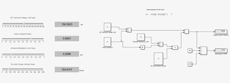
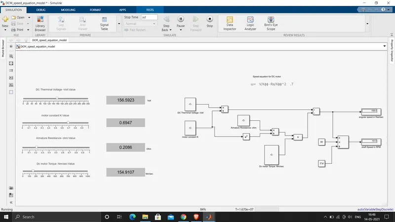
Model.m file attached
4. Refer to the blog on below topic:
Induction Versus DC brushless motors by Wally Rippel, Tesla
Explain in brief about author’s perspective.
==> here the Author's explaining about two technologies, How do they work? What differentiates them? And what do they have in common?
this two technology are Brushless DC motor (BLDC motor) and Induction motor
Author 1st takes BLDC motor to explain it construction and its basic working principle
With brushless machines, the rotor includes two or more permanent magnets that generate a DC magnetic field (as seen from the vantage point of the rotor). In turn, this magnetic field enters the stator core (a core made up of thin, stacked laminations) and interacts with currents flowing within the windings to produce a torque interaction between the rotor and stator. As the rotor rotates, it is necessary that the magnitude and polarity of the stator currents be continuously varied – and in just the right way - such that the torque remains constant and the conversion of electrical to mechanical energy is optimally efficient.
then author takes Induction motor:
the induction rotor has no magnets – just stacked steel laminations with buried peripheral conductors that form a “shorted structure.” Currents flowing in the stator windings produce a rotating magnetic field that enters the rotor. In turn, the frequency of this magnetic field as “seen” by the rotor is equal to the difference between the applied electrical frequency and the rotational “frequency” of the rotor itself.
Conclution:
| BLDC Motor | Induction Motor |
|
-there is a permanent magnet in the rotor rotot cost is more compared to IM |
-peripheral conductors that form a “shorted structure.” rotor cost is less |
| As rotor is permanent magnet difficult handle during assembly | easy to handle |
| Speed is controlled using a PWM drive | speed can be controlled by varing frquency |
| with out a drive BLDC motor is useless | IM can operate without a drive, the motor rotor will rotate at constat speed as per the applied supply frquency |
| peak point efficiency is generally higher | best efficiency for the induction drive at arround 85 percent |
| DC brushless, as machine size grows, the magnetic losses increase proportionately and part load efficiency drops | With induction, as machine size grows, losses do not necessarily grow. |
| BLDC motor generaly used in hybrid type vehical |
IM is prefered in pure EV |