Week-7 Challenge: DC Motor Control
1. A. Explain a MATLAB demo model named ‘Speed control of a DC motor using BJT H-bridge’.
B. Comment on the armature current shoot-up from the scope results.
C. Refer to the help section of ‘The Four-Quadrant Chopper DC Drive (DC7) block’. Compare it with the H-bridge model.
A. Explain a MATLAB demo model named ‘Speed control of a DC motor using BJT H-bridge’.
Aim: To analysis the matlab demo model named speed control of a DC motor using BJT H-bridge.
Open matlab and in command window type power_Hbridge. Then following model will be opened.
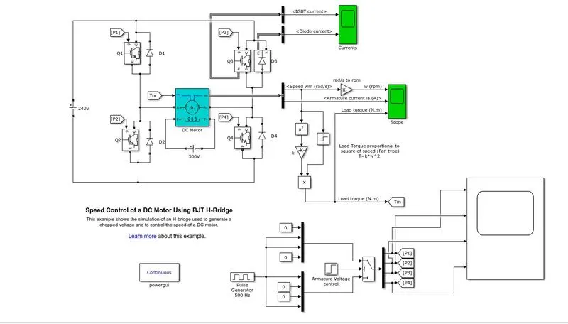
Model Explanation:
1.DC motor:
1.DC machine used for converting Electrical energy into mechincal energy and vice-versa.
2.Forward motoring refers to a converting Electrical energy into mechincal energy and Regenerative braking refers to converting mechincal energy into Electrical energy.
3.To work DC machine as both generator and motor a DC drive ciruit is required.
4.In This model BJT H bridge drive is used.
5.Due to use of BJT switches, these motor cannot operated for braking. This drive model used for Forward motoring and reverse motoring.
2. BJT H bridge:
1. It consist of 4 BJT switches and 4 diodes. This switches and diodes are connected across DC machine as shown in model.
2. when Q1 and Q4 are triggered then positive voltage is appeared across the motor and D2 and D3 act as free wheeling doide.
3. when Q3 and Q2 are triggered then negative voltage is appeared across the motor and D1 and D4 act as free wheeling doide.
3.Pulse Generator:
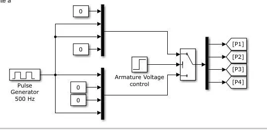
1. Pulse Generator is used to Generate the pulses for BJT.
2. Pulses haiving some frequency is given two 4*1 encoder as shown above. These decoder and armature voltage is applied to controlled switch.
3. From controlled switch it is given to one 1*4 decoder. From this decoder pulses are given to respective BJTs using goto block.
3.If aramature voltage is greater than 2 sec step time, the top encoder will be selected and Q3 and Q2 will be Triggered and motor will opearte in reverse direction.
4.If aramature voltage is Less than 2 sec step time, the bottom encoder will be selected and Q1 and Q4 will be Triggered and motor will opearte in Forward direction.
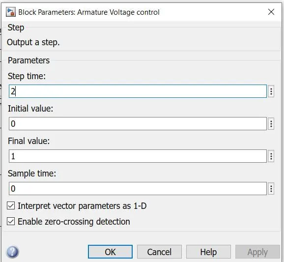
Working:
When positive voltage is applied across DC motor, motor rotate in forward direction. This will happen before 2 sec step time across aramature control voltage block. After 2 secs negative voltage is applied across the motor, so motor rotate in reverse direction.
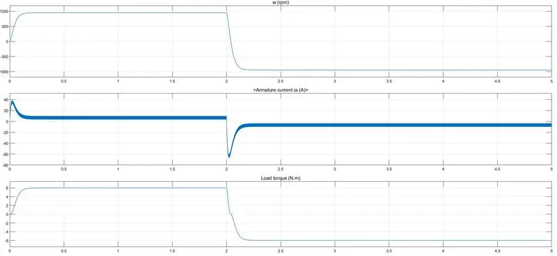
From above graph upto 2 secs speed, aramature current, load torque are positive because motor operating in forward direction.
After 2 secs motor operates in reverse direction.
Speed of motor is 1000 rpm
Aramature current nearly 15 amps
Load torque is 6Nm.
B. Comment on the armature current shoot-up from the scope results.
Case 1: Pulse width is 75%
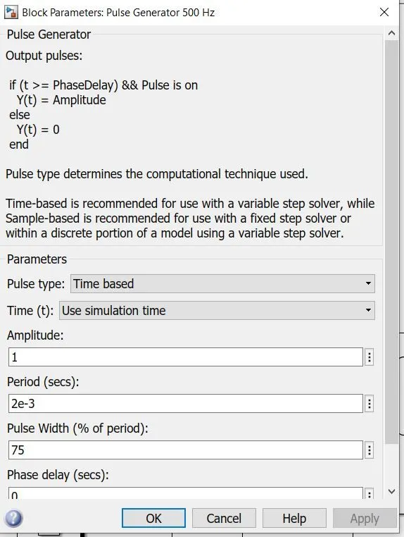
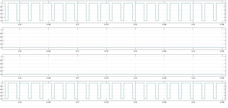
Above 2 figures shows pulses width of BJTs. Pulse width is 75 percent.
Armature peak current is nearly 40 amps. Due to this high currents, motor winding can be damaged. To reduce this aramatur current decrease pulse width of pulse generator.
Speed of motor is 1000 rpm
Aramature current nearly 15 amps
Load torque is 6Nm.
Case 2: Pulse width is 50%
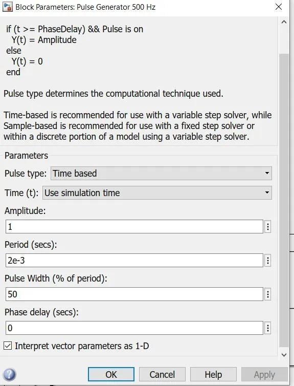
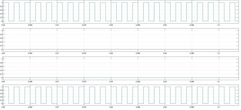
Above 2 figures shows pulses width of BJTs. Pulse width is 50 percent.
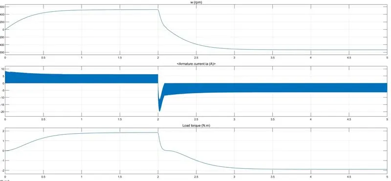
Armature peak current is nearly -18 amps in reverse motoring and 8 amps in forward motoring. Therefore as pulse width decereases then peak current of armature decreases.
C. Refer to the help section of ‘The Four-Quadrant Chopper DC Drive (DC7) block’. Compare it with the H-bridge model.
Problem with scr: SCR switches have greater advantages compare to all switches but due to commutation problem, this switches are not used for four quadrant operation.
Problem with BJT: BJT can't block reverse voltage, due to which regenerative braking is not possible.
Mosfet and IGBTs are best for four quadrant operation of a DC motor.
Open matlab and in command window type dc7_example. Then following model will be opened.
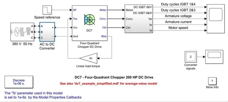
Explanation:
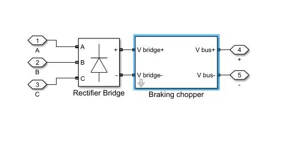
3 phase AC supply is converted to DC supply using Rectifier circuit. Output of Rectifier is given to Type E four quadrant Chopper circuit.
Working is same as BJT H bridge. Instead of using BJT switches, here we are using Mosfet switches. Due to which Regenerative Braking is possible.
Results:
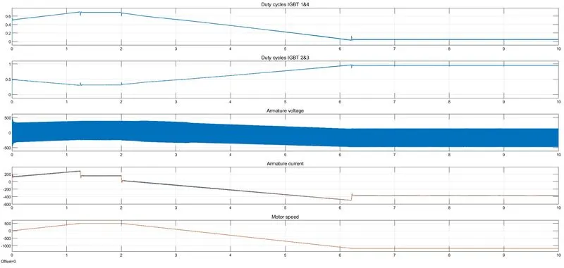
From above figure it can be conculded that motor is operating in four regions. Forward motoring, forward braking, reverse motoring, reverse braking.
Comparison of BJT H bridge and Four-Quadrant Chopper DC Drive
| S.no | BJT H bridge | Four Quadrant Chopper |
| 1 | Two quadrant operation | Four quadrant operation |
| 2 | Forward motoring,reverse motoring are possible. | Forward motoring, forward braking, reverse motoring, reverse braking are possible. |
| 3 | Regenerative braking is not possible due to switch properties | Regenerative braking is possible |
| 4 | Reference speed is not possible as it is open loop system | Reference speed is possible as it is closed loop system |
| 5 | As it is open loop system, aramature current controll is not possible | As it is Closed loop system, aramature current controll is possible |
2.Develop a 2-quadrant chopper using simulink & explain the working of the same with the relevant results. (Refer to article - Multiquadrant operation of motor ).
Aim: To develop a 2-quadrant chopper using simulink
Blocks Required:
1. Powergui
2. DC motor
3.Mosfets
4. Diodes
5. Scope
6. DC voltage source
7. Pulse generator
8. Constant block
Explanation:
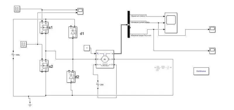
1. DC supply is applied to DC motor along with DC drive.
2. DC drive is nothing but 2 quadrant chopper consist of 2 mofets and 2 diodes and connected as shown above.
3.Pulse generators are used to trigger Mosfet for drive operation.
4.Torque of 1Nm is applied to DC machine using constant block.
Working:
1st quadrant operation
when s1 is on and s2 is off, then positive vdc is applied across the motor. At this time voltage and current are positive.
Motor will rotate in forward direction.
2nd quadrant
when s2 is on and s1 is off, voltage appiled across the motor is positive, but aramature current is negative.
It is forward regenerative mode.
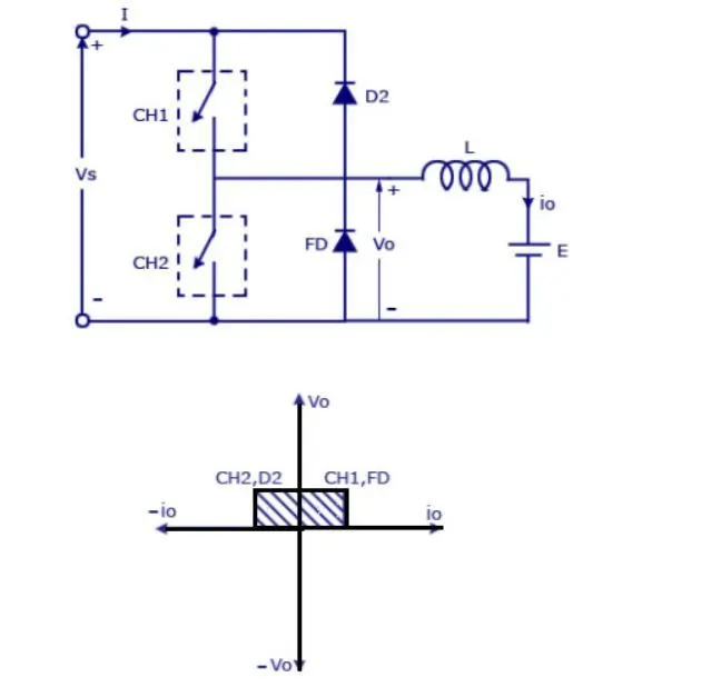
Entire model was simulated for 10 secs and pulses are Given accordingly to Mosfets.
Pulse generator:
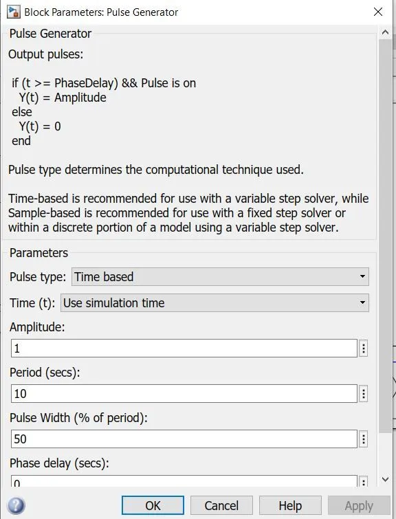
This pulse generator values are applied to Mosfet s1.
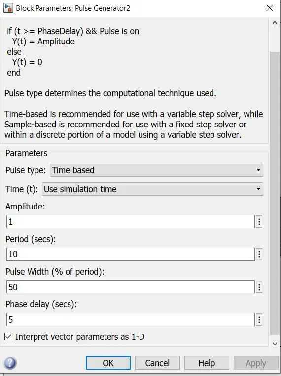
This pulse generator values are applied to Mosfet s2 having phase delay of 5 secs.
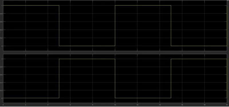
above figure shows how the the pulses are applied across mosfets.
Results:
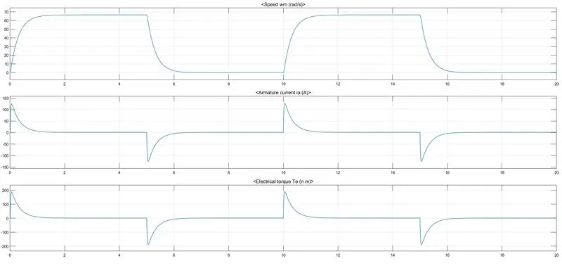
S1 is on for 5 secs, at that time motor is rotating in forward direction. speed reaches to 60 rads/s , aramture current is nearly 0.8 amps and load Torque is 1Nm
At t=5 S1 is off and S2 is on, at time forward Regenerative braking is applied and speed reaches to zero.
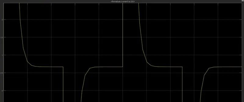
Above figure shows aramature current value.
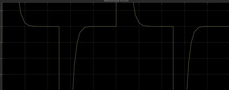
Above figure shows Load Torque value.
Conclusions:
1 2 quadrant chopper for DC motor has been developed for DC motor which will operated as forward motring and forward braking.
2.At starting Aramature current peak value is nearly 120A. This peak current can cause damage to the windings.
3. To reduce this starting current a starter is used.
3. Explain in a brief about operation of BLDC motor.
Ans:
Brushless DC motors, is a special kind of permanent magnate synchronous motor.
Permanent magnet synchronous motors are classified on the basis of the wave shape of their induce emf, i.e., sinusoidal and trapezoidal.
The sinusoidal type is known as permanent magnet synchronous motor,the trapezoidal type goes under the name of PM Brushless dc (BLDC) machine.
Current in the DC motor is automatically switched to different windings by means of a commutator and brushes to create continuous motion.
In Bldc motor commutation is implemented electronically with a drive amplifier that uses semiconductor switches to change current in the windings based on rotor position feedback.
Types of bldc motors:
Unipolar
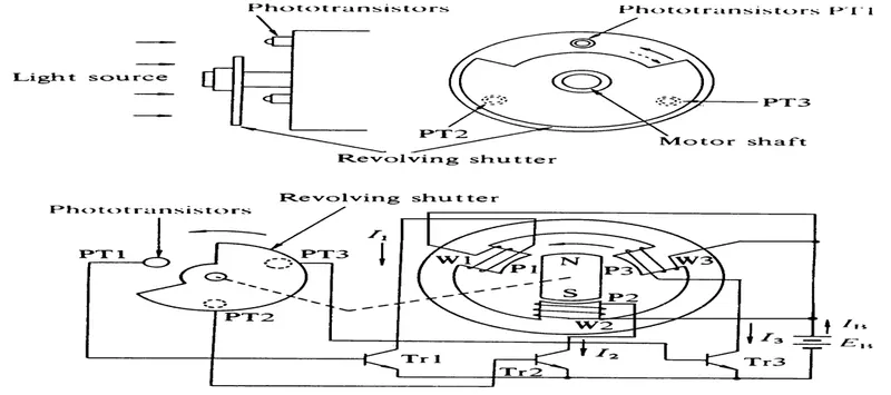
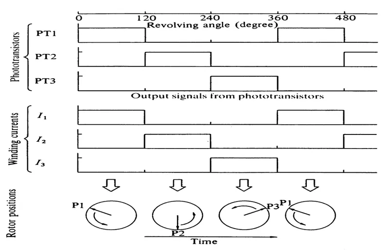
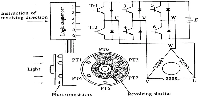
2. Bi polar
Hall sensor
- To rotate the BLDC motor, the stator windings should be energized in a sequence.
- It is important to know the rotor position in order to understand which winding will be energized following the energizing sequence.
- Rotor position is sensed using Hall effect sensors embedded into the stator. Most BLDC motors have three Hall sensors embedded into the stator on the non-driving end of the motor.
- Whenever the rotor magnetic poles pass near the Hall sensors, they give a high or low signal, indicating the N or S pole is passing near the sensors
Working
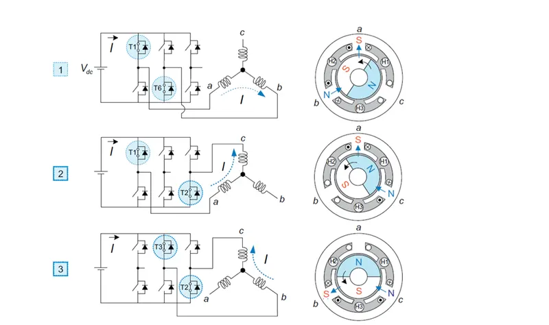
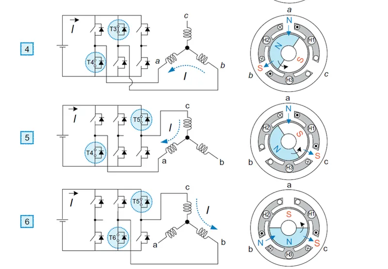
Operating sequence
switcing sequence:
T1,T6 : T1 carries A phase positive current and T6 carries B phase negative current.
T1,T2 : T1 carries A phase positive current and T2 carries C phase negative current.
T3,T2 : T3 carries B phase positive current and T2 carries C phase negative current.
T3, T4 : T3 carries B phase positive current and T6 carries A phase negative current.
T5, T4 : T5 carries C phase positive current and T6 carries A phase negative current.
T5,T6 : T5 carries C phase positive current and T6 carries B phase negative current.
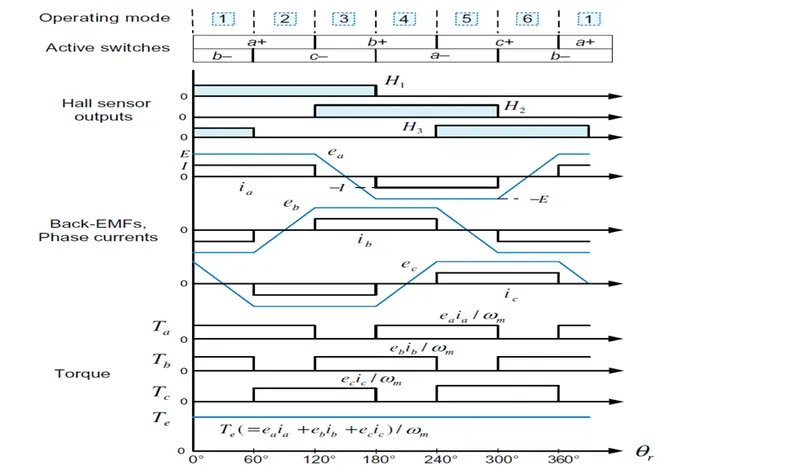
At any instant Two swtiches are conducting one is from Positive group and another is from negative group. Resultant of all the switches will rotate motor in clock wise direction.
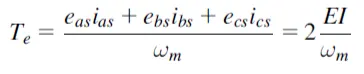
Above equation represents torque equation of BLDC motor. As only two phases are conducting at a time, current in other phase will be zero.
Characteristics of BLDC motor:
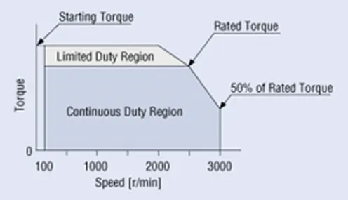
Advantages of BLDC motor:
They are employed in Military, Drives and Robotics etc. for the following advantages:
- Compactness in size.
- High starting torque.
- High speed operation.
- Low inertia.
Disadvantage:
- Cost of motor is very high
- Resonance issue
- Due to electronic switches, winding of a machine is very complex.
Application
- EV drives
- Military operation
- Robotics