Week - 4
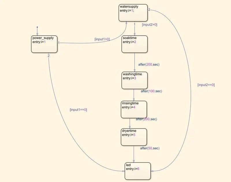
- Implement control logic of a “washing machine” using Stateflow as per given sequence:
- If the power supply is available, the system gets activated
- If the Water supply is not available, stop the process & indicate through LED
- Soaking time should be 200s followed by Washing time of 100s.
- Then rinsing happens for next 20s & dryer runs for 50s
Aim: To implement control logic of a washing machine for various conditions.
Blocks Required to implement simulink model
1. powergui : Used to give power supply to entire system
2. constant : This block is uesd for powersupply, water supply
3. chart: It is used for creating state transitions and control logic
4.scope: It is used for showing result
5. Lamp : For particular condition corresponding led will grow.
Theory:
State Flow:
state flow is a graphical represntation of a flow chart diagrams and state transition diagrams. Instead of Coding , this technique is used and it can easily understanble( userfriendly).
In Transition diagram, based on conditions the blocks are implemented.
Control design:
Based on requirement a control logic is desinged for a model system.
Explanation:
Condition:
- If the power supply is available, the system gets activated
- If the Water supply is not available, stop the process & indicate through LED
- Soaking time should be 200s followed by Washing time of 100s.
- Then rinsing happens for next 20s & dryer runs for 50s
Based on above conditions state Trasnstion diagram is created as shown in fig.
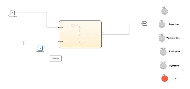
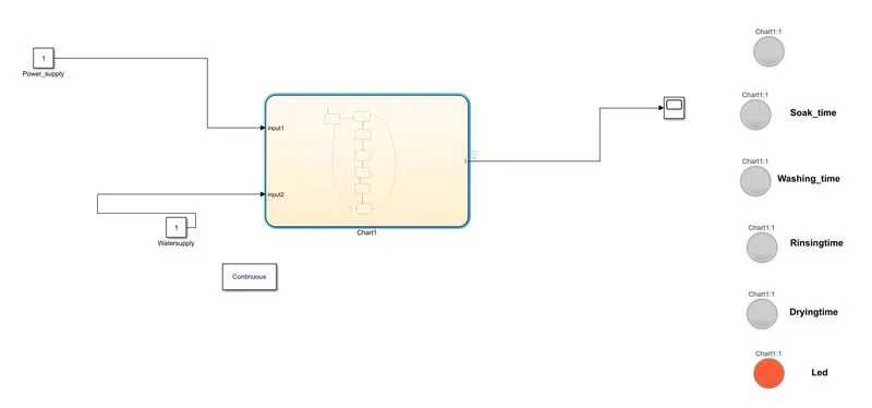
step1: If power supply and water are availabe to the system then this logic will be implemented. If there is no power supply and water then this logic is not implemented on washing machine and led will show orange colour as show below fig.
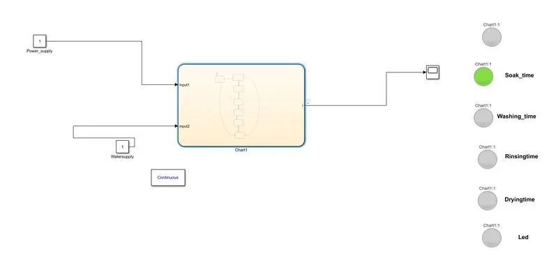
Step2: If power supply and water are availabe to the system then this logic will be implemented. This can be done by changing input values of correspondind constant blocks to 1.
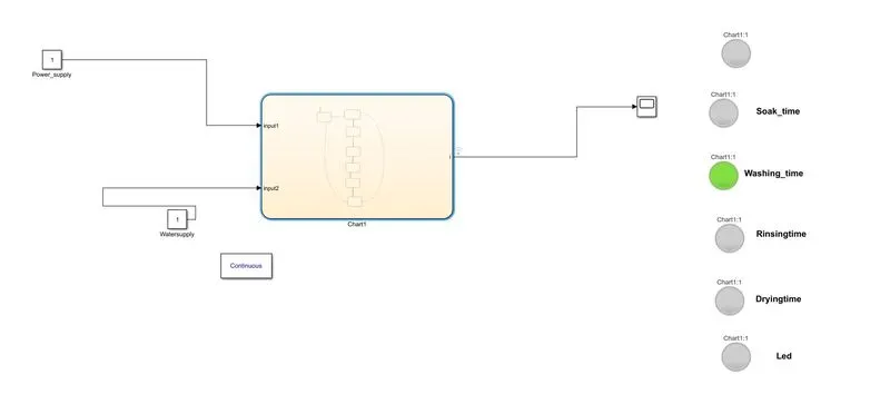
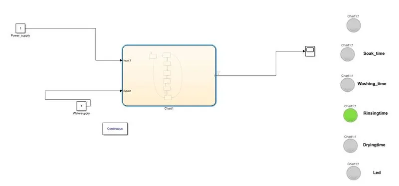
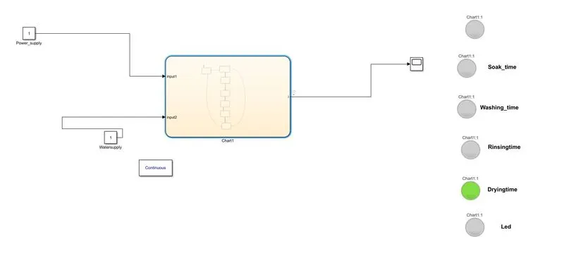
Based on delay time corresponding block will implemented and correesponding lamp will glow.
As to diffrentiate the various stages of washing, simulation time has been changed.
Soak Time:
Washing time
Rinsing Time
Drying Time
Final step
After completing washing, finally Led will grow orange
Procedure:
- Open matlab,simulink and create new slx file , connect the circuit as show above figure
- Based on the given conditions write the steps in transtion blocks.
- simulate the observe each state of the system by observing lamps.
- plot the results using scope.
Scope result:
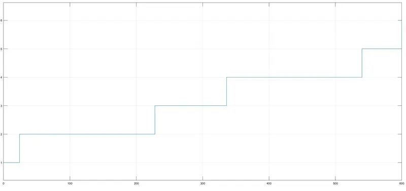
Result:Control Logic for a washing machine was implemented and Results are ploted.
2.Make a Simulink chart for the “Gear shift” logic as per below conditions:
Speed Range(kmph) Gear
0 to 15 1
16 to 25 2
26 to 40 3
41 to 60 4
Above 61 5
Give speed input while the simulation is running & display the gear number.
Aim: To design Gear shift logic for a given system.
Blocks used:
1.Chart : used for wirting Transation sates using given conditions
2.lamp : used to Indicate which gear was system operating
3. constant block: used for creating accelerator and Igintion for system
4. Gauge: Shows the speed of the system
5.Slider: used for change the speed of the system while simulation is running.
6.Display: used to Indicate which gear was system operating.
Theroy:
State Flow:
state flow is a graphical represntation of a flow chart diagrams and state transition diagrams. Instead of Coding , this technique is used and it can easily understanble( userfriendly).
In Transition diagram, based on conditions the blocks are implemented.
Control design:
Based on requirement a control logic is desinged for a model system.
Explanation:
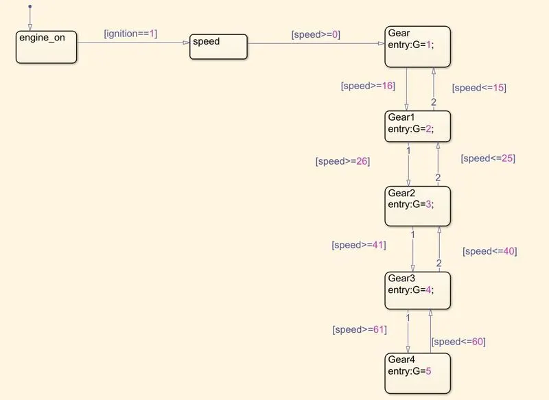
Conditions:
Speed Range(kmph) Gear
0 to 15 1
16 to 25 2
26 to 40 3
41 to 60 4
Above 61 5
Based on above conditions state diagram has been created as shown below.
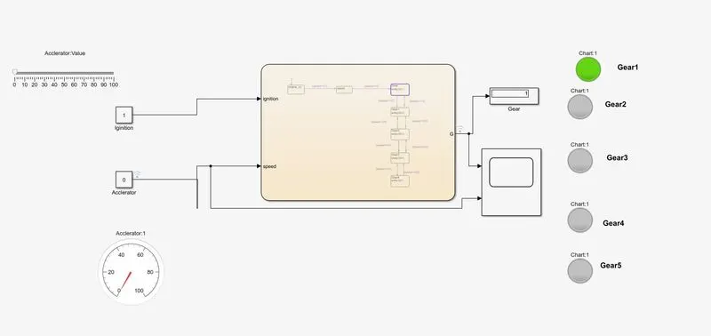
Apply Ignition and accleration to the system.Accleration of the system can be varied using slider gain. As accleration changes gears of the system can be changed.
If speed varies between 0 to 15 then system is in frist gear as shown below
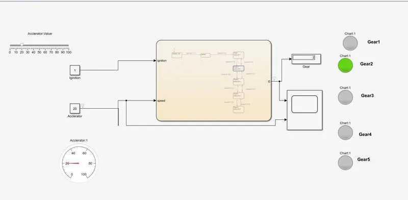
If speed varies between 16 to 25 then system is in second gear as shown below
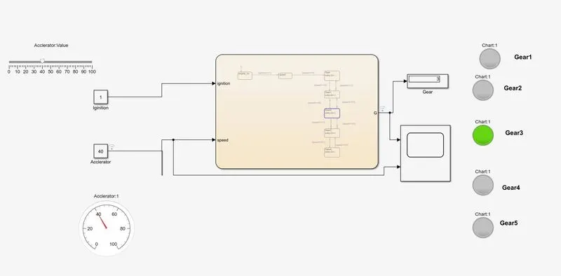
If speed varies between 26 to 40 then system is in Third gear as shown below
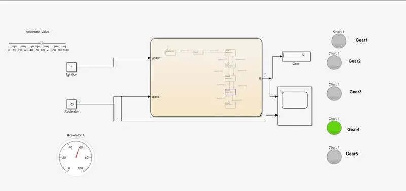
If speed varies between 41 to 60 then system is in Fourth gear as shown below
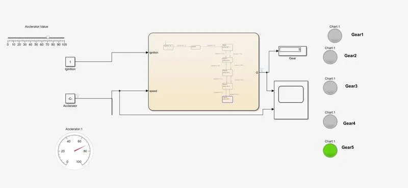
If speed varies above 60 then system is in Fifth gear as shown below
Procedure:
- Open matlab,simulink and create new slx file , connect the circuit as show above figure
- Based on the given conditions write the steps in transtion blocks.
- simulate the observe each state of the system by observing lamps.
- plot the results using scope.
Scope Results:
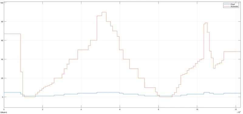
Result:
For Given conditions,Gear system was designed using matlab. By changing speed we can observe that at what gear system is operating.