Week -2
1.Make a Simulink model of Doorbell using solenoid block with the following details
Aim: To implement simulink model for doorbel using solenoid
Blocks required to implement model:
1. pulse Generator
2. Simulink to Ps converter
3. Ps to simulink converter
4.Slover Configuration
5. Battery (12V, 2ohms)
6. Switch
7. solenoid
8. Ideal Translational motion Sensor
9. Scope
10. Display, Electrical and mechanical Reference.
Theory:
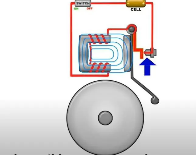
whenever current passes through any conductor, it produces a magnetic field around it. Soleniod is a iron piece where conductor is wound around it, when current passes through soloniod it behaves like a electromagnet. A Metal portion is placed near this solenoid, to this metal portion a plunger is connected as shown in electrical bell daigram. Near to plunger a small bell is placed.
working: when current passes through soleniod, it attracts metal peiece near to it, as plunger is connected to this metal portion, it will directly hit the bell.
Role of Pulse generator: pulse generator give pulses for cetain duration only. As per question, Pulses are required for only 2 secs. so Pulse Generator is desinged to give pulses for only for 2 secs.
Pulse generator is connected to switch. Based on pulses, switch will turn on and turnoff. when switch is turn on , soleniod will behave like electromagnet and same process will repeat as expalined on working. when switch is turn off, Soleniod will become non electromagnet and it will relases the plunger.
Procedure:
1: Open Matlab, simulink file and connect the circiut as shown in doorbell slx file
2: After compiling save the file .
Simulink Diagram Explanation:
1. Battery, Switch, conductor(coil) are connected in series. A slover configuration, Electrical References are connected to negative Terminal of battery. Pluse generator is connected to Switch.
2. Movement of Plunger of Soleniod can be sensed using ideal translational motion sensor, so it is connected in series.
3. Scope is connected to Ideal translational Motion sensor and pulse Generator, where output can be seen.
Results:simulink model for doorbel using solenoid is Implented. Conditions for closing Switch for 2 seconds was Implemented.
2. Use a thermistor to sense the temperature of a heater & turn on or turn off the fan as per below conditions:
Aim:1) To sense the temperature of a heater & turn on or turn off the fan using Thermistor and Build the model in simulink
2) Based On Given conditions turn on Fan for a particular temperature.
Blocks Required for this model:
1.Signal Bulider
2.Simulink to Ps connector and Ps connector to Simulink
3. Controlled Temperature Source
4. Slover Configuration
5.Thermal and electrical Reference
6.Battery
7. Thermistor
8. Resistor
9. Voltage Sensor
10. Conditional switch
11. Simulink
12.Powergui
13. Display
14.Adder.
Working:
Thermistor is a device which is used to sense the Temperature of its surroundings with the help of its resistance. Volatge sensor is connected across the thermistor resistance which senses voltages under various Temperatures.
a) Conditions
Temperature source: 20 °C from 0 to 10 seconds, 27 °C from 10 to 30 seconds, 23 °C from 30 to 50 seconds
Fan conditions: ON if the temperature above 25 °C, OFF otherwise
As per Conditions when Tempertaure is above 25°C, Voltage sensor should sense corrsponding voltage and turn on the switch, which is connected to fan.
In this Case corresponding voltage to be found as 0.01284V. so for this voltage above values switch should be turn on otherwise it should be turn off.
Procedure:
1) open Matlab and simulink, create new model, and connect the circuit as shown in temperature slx file.
2) save and compile the file
Simulink Diagram Explanation:
1) Signal Bulider is used to build the various Temperture required for this model.
2) From signal Bulider it is connected to controlled Temperature sensor via simulink to ps Connector.
3) From controlled Temperature sensor it is connected to thermistor.
4)Thermistor is in series with the battery and negative terminal of battery is connected to electrical Reference.
5) Volatge sensor is connected to thermal resistance of thermistor and produce to signals to switch to either turnon or turnoff the fan based on corresponding voltage for corresponding Temperature.
Results:Simulink model was devloped and conditions are Implemented.
\