Week-7 Challenge: DC Motor Control
AIM:
- To run MATLAB demo 'speed control of a dc motor using BJT H- bridge Modify the model such that armature current doesn't shoot up when motor changes direction from forward to reverse.
- To understand the four quadrant chopper Dc drive (DC7) block and compare it with H-bridge model.
- To make a suitable EV model using DC7 block and make result report.
- Explain in a brief about operation of BLDC motor.
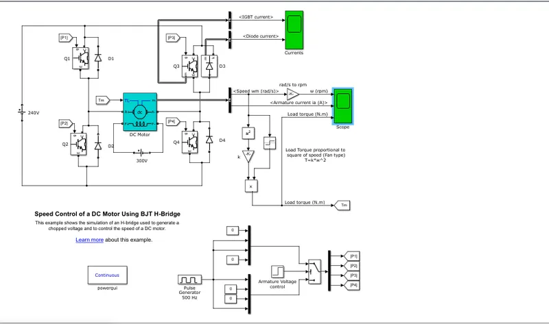
1. The Bipolar junction transistor when used for power switching applications operates as an IGBT. When it is conducting (when BJT operating in saturated region) a forward voltage Vf is developed between collector and emitter (in the range of 1v). Therefore IGBT block can be used to model the BJT device.
The IGBT block does not simulate the gate current, controlling the BJT or IGBT. The switch is controlled by the Simulink signal (1/10). The DC motor uses the present model (5 HP 24 V 1750 rpm). it simulates a fan type load. The armature mean voltage can be varied from 0 to 240 v when the duty cycle is varied from 0 to 100%
The H-Bridge consist of four BJT/Diode pairs (BJT simulated by IGBT models). Two transistors are switched at the same time. Like Q1 and Q4 or Q2 and Q3. When Q1 and Q4 are fired a +ve voltage is applied to the motor and diodes D2 and D4 operate as when Q2 and Q3 are switched off.
When the simulation is run the motor starts in the +ve direction with a duty cycle ratio of 75% at t=0.5 sec the Va (armature voltage) is suddenly reversed and the motor runs in the negative direction.
Scope shows the motor speed, Armature current and load torque.
Plot :
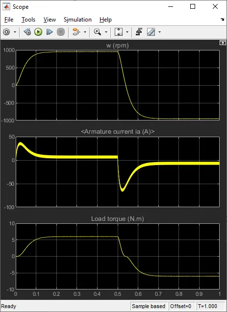
As we can see from the above graph the armature current reverses and shoot up and suddenly at t=0.5 sec so we have to modify such that the armature current doesnt shoot up when the motor reverses its direction by changing the duty cycle ratio
Modification:
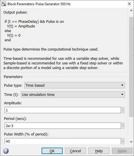
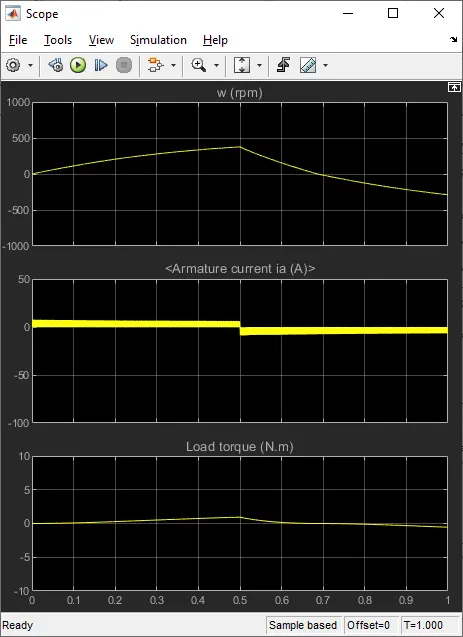
The duty cycle ratio changed to 45% which is given by the pulse generator block after changing the duty cycle we get the out put as the plot below
PLOT:
2. The Four Quadrant Chopper DC drive:
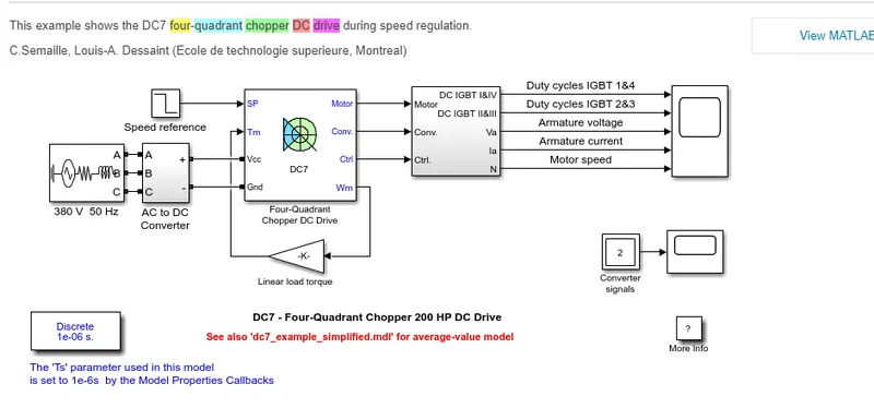
The 200Hp Dc motor is seperately exicited with a constant 150V DC field voltage. The armature voltage is provided by an IGBT converter controlled by the two PI regulators. The converter is fed by a 515V DC bus obtained by rectification of 380V AC 50Hz voltage source. In order to limit the DC bus voltage during dynamic braking mode a braking chopper has been added between the diode rectifier and DC7 block.
The first regulator is a speed regulator follwed by a current regulator the spped regulator outputs the armature current reference used by the current controller in order to obtain the electromagnetic torque needed to reach the desired speed. The spped referennce change rate follows acceleration and decelaration ramps in order to avoid sudden reference changes that could cause armature over current and destablise the system.
The current regulator controls the Armature current by computing the appropriate duty ratios of the 5KHZ pulses of the four IGBT devices popularly kniwns as Pulse width modulation. For proper system behaviour the instantaneous pulse values of IGBT devices 1 and 4 are opposite to those pulse values of IGBT devices 2 and 3. This generated the average armature voltage needed to obtain the desired armature current. In order to limit the amplitude of the current oscillations a smoothing inductance is placed in series with armature circuit
The main disadvantage of this drive compared with other Dc drives is that it can operate in all four quadrants (forward motoring, reverse generation, reverse motoring, forward generation) in addition due to high switching frequency DC-DC converters, a lower armature current ripple (compared with Thyristor based DC drives) obtained however four switching devices are required which makes it costly and complex as well in the drive system
EV modelling using DC7 block:
To create a new model
Load torque
Power supply
Drive cycle
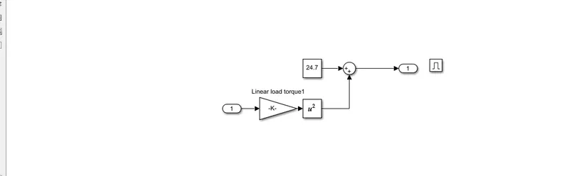
Load torque input:
For the torque input the speed torque characterstics equation
T= 24.7 +0.0051*w^2
Simulation:
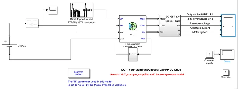
The drive cycle with speed and time is simulated with the 100v DC supply through the load torque unit.
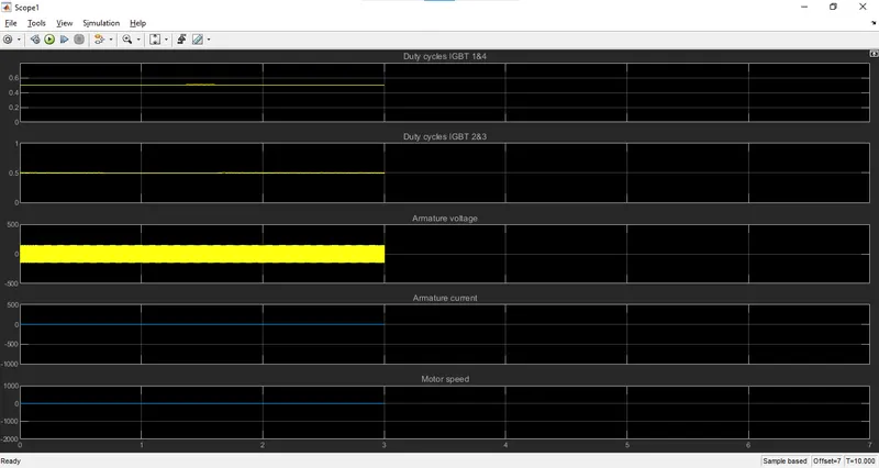
The motor speed, armature, current, armature voltage are simulated with the duty cycle in the four quadrant chopper device.
At certain time the armature current gets reveresed and the braking torque is produced this increase the DC voltage.
The motor speed is mismatched thus the EV model is created using the four quadrant dc drive.
Comparing it with the H-bridge model with DC7 block:
DC Four quadrant chopper :
- The armature voltage is provided by IGBT controllers is controlled by PI regulatior
- The braking chopper has been added between the diode andd motor.
- This model contains speed and current regulatiors
- The speed regulator repreents armature current controller in order to obtain the electromagnetic torque needed to reach the desired speed.
- The chopper converts fixed DC into variable DC voltage
- It requries current for each sector and consists of four quadranrs such as Forward motoring,reverse motoring, forward regenerative braking reverse regenerative braking
- Current signal is interrupted with one other to change the direction of the motor.
- PID controller is used in DC7 drive
- Change in direction in BJT is doe by changing polarity
H-Bridge model:
- It consist of two operartions forward motoring and reverse motoring
- Regenerative braking is not possible but dynamic braking is possible
- The current values are continous
- They are widely used in robotics and electromechanical devices to control DC motor speed and direction
- To change the direction of motor only to polarity of current is changed
3.To explain in a brief about operation of BLDC motor:
BLDC motor consist of a stator and rotor stator windings of a BLDC motor are connected to a control circuit the circuit energizes proper winding at proper time in a pattern which rotates around the stator.
The rotor magnet tries to aligin with energized electromagnet of the stator and as soon as it aligins the next electromagnet is energized thus the rotor keeps rotating.
In BLDC motor we generaly dont use commutator in order to get unidirectional torque integrated circuit is used to get unidirectional torque.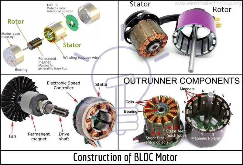
Advantages of BLDC Motor:
- Higher efficiency and reliablity
- Lower acoustic noise
- Smaller and lighter
- Greater and Dynamic response
- Higher speed range
- Longer life
Outcomes of this challenges:
Explained the MATLAB demo model named ‘Speed control of a DC motor using BJT H-bridge’.
and plotted the armature current shoot-up from the scope results.
Compared the The Four-Quadrant Chopper DC Drive (DC7) block with H-bridge model.
2. Developed a 4-quadrant chopper using simulink & explained the working of the same with the relevant results.
3. Explained in a brief about operation of BLDC motor.