Week -2
Aim:1.To Make a Simulink model of Doorbell using solenoid block
- 2. Use a thermistor to sense the temperature of a heater & turn on or turn off the fan
- 1.Door bell
- Blocks used to develop the model:
- Dc voltage source
- Switch
- Ideal translation motion sensor
- Solenoid
- Scope (2 no)
- Pulse generator
- Solver function
- PS-simulink
- Simulink block model:
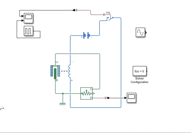
- Block connections:
- The pulse generator is used to create square wave pulses. we can change the shape and pulse width but changing the parameters of the block by double clicking
- The switch block is controlled by external physical signal if external signal is greater than thresold value the switch is closed or else the switch is open.
- the solenoid block is connected with switch and battery and we will get a complete circuit port c of the solenoid is connected to mechaniScal reference.
- The ideal translation sensor is connected to solenoid's R terminal to observe the movment
- Scope is connected with ideal translational sensor to get the output
- PS simulink converter is used physical signal to simulink signal
- The Solver configuration each physical network represented by a connected simscape blocks requires solver setting information for simulation.
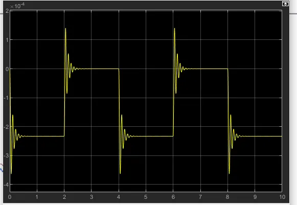
- Output graph:
- 2.THERMISTOR
- Aim:Use a thermistor to sense the temperature of a heater & turn on or turn off the fan
- Condition :
- The should on only if the temperature is abovr 25 degrees
- Blocks used to delevop the model:
- Thermistor
- Switch
- PS-simulink
- Solver configuration
- Battery source
- Constant
- Display
- Ground reference
- Resistor
- Ground reference
- Thermal reference
- Display
- Voltage sensor
- Scope
- Block diagram:
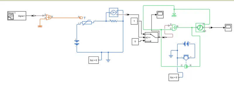
- In the above block diagram the controlled temperature source the values of the temerature are taken as kelvin.
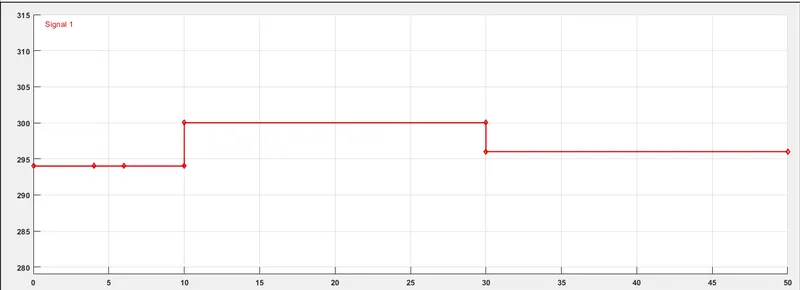
- For the values the 3 inputs is given in the period of 20'C, 27'C and 23'C
- it is the connected to the controlled temperature source block through PS-converter
- It is connected to thermistor to give resistance in accordance with the input tempearture.
- A voltmeter is connected in parallel to the reisitor in which in series ti thermistor since same resistance will be exhibited by the resistor
- An solver configuration and an electrical references provided to the circuit as well
- Input signal graph:
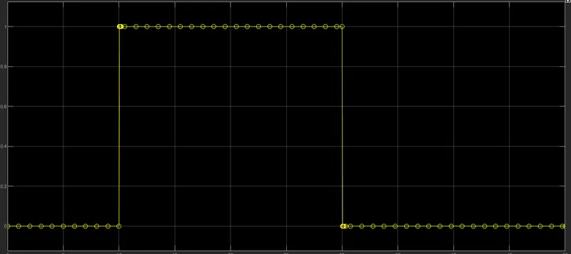
- Output graph for switch:
- Electrical to Mechanical conversion:
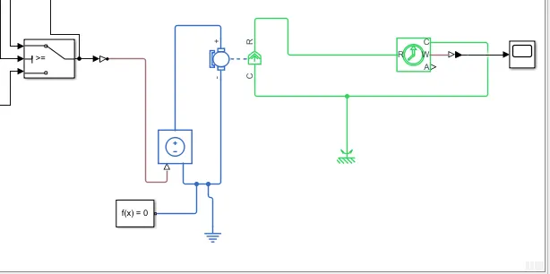
- Output from the switch is given to the velocity source which is connected to a DC motor with a battery source
- to plot the motion fan a rotational motion sensor is connected
- mechanical and electrical references should be provided to the respective sources
- Motion of the fan is plotted by the scope block by using PS simulink converter.
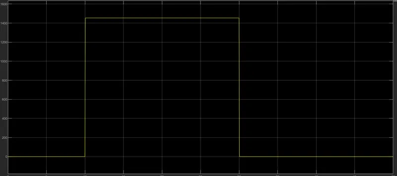
- Output graph:
- Conclusion:
- it is inferred that only when temperature exceeds over 25'C that is at 27''C from 10 to 30 seconds of time the fan shows displacement from the output scope
- Hence, the condition given is satisfied