Week-7 Challenge: DC Motor Control
1 A TO HAVE A DETAILED STUDY ABOUT SPEED CONTROL OF A DC MOTOR USING BJT H-BRIDGE.
B TO DESCRIBE ON THE ARMATURE CURRENT SHOOT UP FROM THE SCOPE RESULTS
C TO COMPARE THE FOUR QUADRANT CHOPPER DC DRIVE(DC7) WITH HBRIDGE MODEL
OBJECTIVES
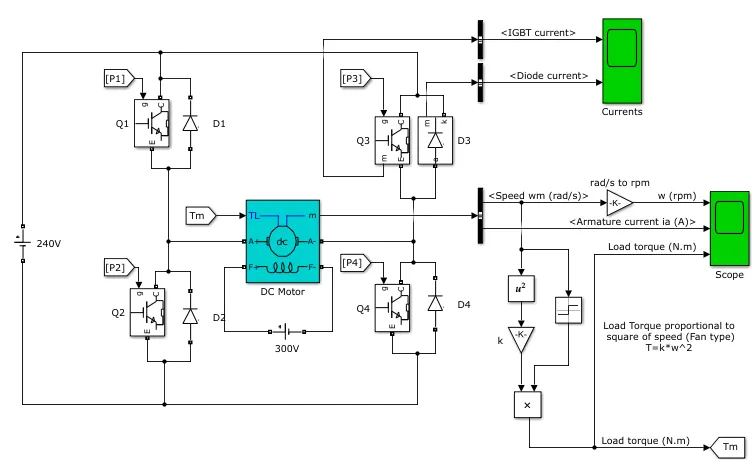
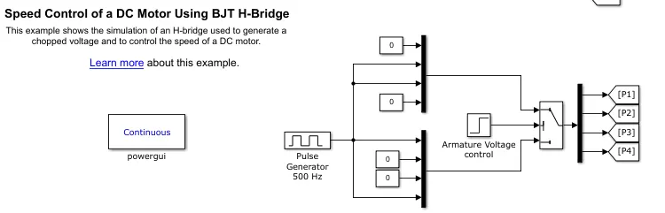
1 This figure shows the BJT H bridge used to control a DC motor.
DESCRIPTION
The Bipolar Junction Transistor (BJT) when used for power switching applications, operates as an IGBT. When it is conducting (BJT operating in the saturated region), a forward voltage Vf is developed between collector and emitter (in the range of 1 V). Therefore, the IGBT block can be used to model the BJT device.
The IGBT block does not simulate the gate current controlling the BJT or IGBT. The switch is controlled by a Simulink signal (1/0). The DC motor uses the preset model (5 HP 24V 1750 rpm). It simulates a fan type load (where Load torque is proportional to square of speed). The armature mean voltage can be varied from 0 to 240 V when the duty cycle (specified in the Pulse Generator block) is varied from 0 to 100%.
The H-bridge consists of four BJT/Diode pairs (BJT simulated by IGBT models). Two transistors are switched simultaneously: Q1 and Q4 or Q2 and Q3. When Q1 and Q4 are fired, a positive voltage is applied to the motor and diodes D2-D3 operate as free-wheeling diodes when Q1 and Q4 are switched off. When Q2 and Q3 are fired, a negative voltage is applied to the motor and diodes D1-D4 operate as free-wheeling diodes when Q2 and Q3 are switched off
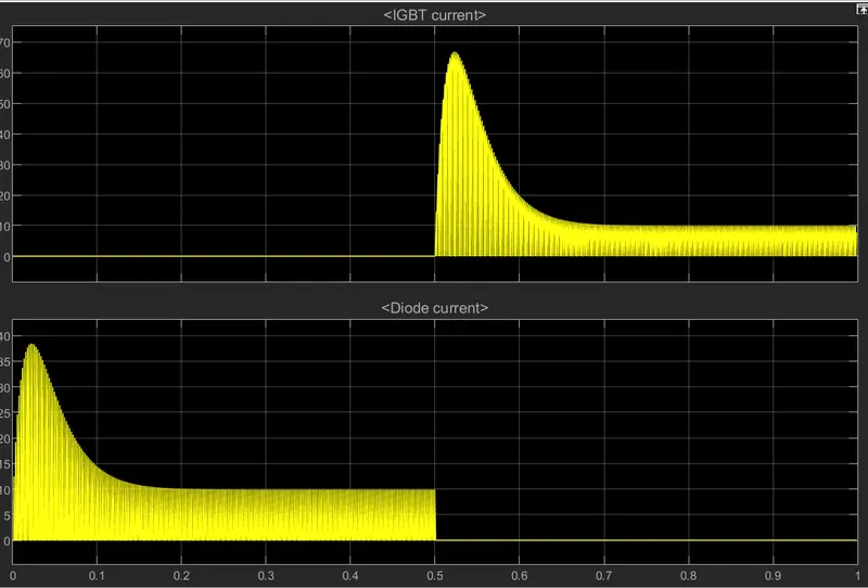
Currents'shows currents flowing in BJT Q3 and diode D30
B Scope shows motor speed, armature current and load torque
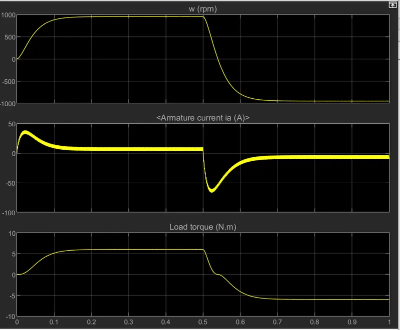
.On first graph is clearly visible that the torque is proportional to torque
.On second graph The motor starts in the positive direction with a duty cycle of 75% At t= 0.5 sec., the armature voltage is suddenly reversed and the motor runs in the negative direction.
.On third graph A torque of 6 Nm is applied initially and the torque goes negative at same magnitude and the motor rotates reversly.
C THE FOUR QUADRANT CHOPPER DC DRIVE 7
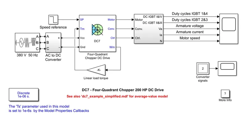
The 200 HP DC motor is separately excited with a constant 150 V DC field voltage source. The armature voltage is provided by an IGBT converter controlled by two PI regulators. The converter is fed by a 515 V DC bus obtained by rectification of a 380 V AC 50 Hz voltage source. In order to limit the DC bus voltage during dynamic braking mode, a braking chopper has been added between the diode rectifier and the DC7 block.
The first regulator is a speed regulator, followed by a current regulator. The speed regulator outputs the armature current reference used by the current controller in order to obtain the electromagnetic torque needed to reach the desired speed. The speed reference change rate follows acceleration and deceleration ramps in order to avoid sudden reference changes that could cause armature over-current and destabilize the system. The current regulator controls the armature current by computing the appropriate duty ratios of the 5 kHz pulses of the four IGBT devices (Pulse Width Modulation). For proper system behaviour, the instantaneous pulse values of IGBT devices 1 and 4 are opposite to those of IGBT devices 2 and 3. This generates the average armature voltage needed to obtain the desired armature current. In order to limit the amplitude of the current oscillations, a smoothing inductance is placed in series with the armature circuit.
H BRIDGE CHOPPER MODEL
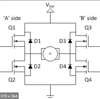
The H-bridge consists of four BJT/Diode pairs (BJT simulated by IGBT models). Two transistors are switched simultaneously: Q1 and Q4 or Q2 and Q3. When Q1 and Q4 are fired, a positive voltage is applied to the motor and diodes D2-D3 operate as free-wheeling diodes when Q1 and Q4 are switched off. When Q2 and Q3 are fired, a negative voltage is applied to the motor and diodes D1-D4 operate as free-wheeling diodes when Q2 and Q3 are switched off
COMPARISON
Four quadrant dc chopper can work in forward motoring,forward braking, reversemotoring and reverse braking(4)modes where as H bridge can only work in forward and reverse(2) modes
Four quadrants always have good efficiency and high energy storage than H bridge.
Regenerative Braking is possible in four quadrant while not possible in H bridge however dynamic braking is possible in H bridge.
Four quadrant dc choppers are widely used in automobiles whereas H bridge are used in robotics.
2 TWO QUADRANT CHOPPER
The Two-Quadrant Chopper block represents a two-quadrant controlled chopper for converting a fixed DC input to a variable DC output.
A simulink model of two quadrant is developed inorder to explain the details.The required devices are
DC voltage source
MOSFET
Pulse Generator
Diodes
Inductor
Logical operator (NOT)
This is the model developed
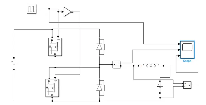
Two mosfets are connected in parallel with dc source.
two diodes are also connected in parallel withit.
An inductor is connected with another dc source in parallel with the second diode
current and voltage measurements are used to measure the current and voltage respectively.
Inorder not to short circuit between the mosfets working, a logical not is connected to both so that only one mosfets works at a time.
scope is connected to pulse generator,current measurement and voltage measurement to have a detailed study of how the output of 2 quadrant chopper works.
output
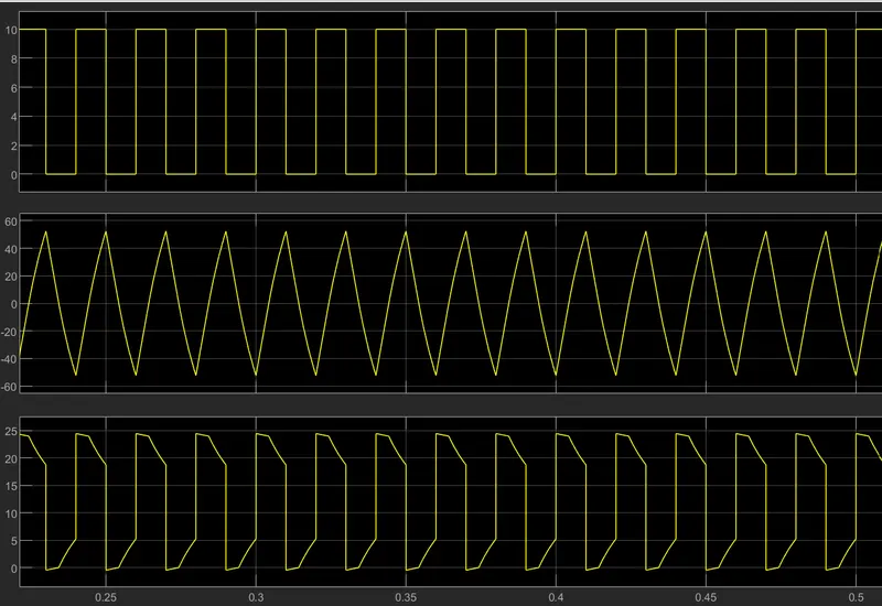
The first grpah is the pulse generated waves
The second one is the current graph which is clearly visible that it varies in both negative and positive sides.
The third graph is the voltage which doesnt go to negative values and keeps thge positive voltage.
3 BRUSHLESS DC MOTORS
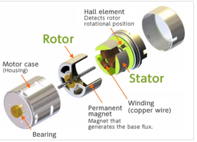
As their name implies, brushless DC motors do not use brushes. With brushed motors, the brushes deliver current through the commutator into the coils on the rotor. So how does a brushless motor pass current to the rotor coils? It doesn’t because the coils are not located on the rotor. Instead, the rotor is a permanent magnet; the coils do not rotate, but are instead fixed in place on the stator. Because the coils do not move, there is no need for brushes and a commutator.
With the brushed motor, rotation is achieved by controlling the magnetic fields generated by the coils on the rotor, while the magnetic field generated by the stationary magnets remains fixed. To change the rotation speed, you change the voltage for the coils. With a BLDC motor, it is the permanent magnet that rotates; rotation is achieved by changing the direction of the magnetic fields generated by the surrounding stationary coils. To control the rotation, you adjust the magnitude and direction of the current into these coils.
ADVANTAGES
One big advantage is efficiency, as these motors can control continuously at maximum rotational force (torque). Brushed motors, in contrast, reach maximum torque at only certain points in the rotation. For a brushed motor to deliver the same torque as a brushless model, it would need to use larger magnets. This is why even small BLDC motors can deliver considerable power.
The second big advantage—related to the first—is controllability. BLDC motors can be controlled, using feedback mechanisms, to delivery precisely the desired torque and rotation speed. Precision control in turn reduces energy consumption and heat generation, and—in cases where motors are battery powered—lengthens the battery life.
BLDC motors also offer high durability and low electric noise generation, thanks to the lack of brushes. With brushed motors, the brushes and commutator wear down as a result of continuous moving contact, and also produce sparks where contact is made. Electrical noise, in particular, is the result of the strong sparks that tend to occur at the areas where the brushes pass over the gaps in the commutator. This is why BLDC motors are often considered preferable in applications where it is important to avoid electrical noise
APPLICATIONS
Because of their efficiency and longevity, they are widely used in devices that run continuously. They have long been used in washing machines, air conditioners, and other consumer electronics; and more recently, they are appearing in fans, where their high efficiency has contributed to a significant reduction in power consumption