DC Motor Speed control and four quadrant chopper
AIM- To understand about the control of DC motor using power converter circuits in Simulink.
OBJECTIVES-
- Run MATLAB demo ‘Speed control of a DC motor using BJT H-bridge’. Modify the model such that armature current doesn’t shoot up when motor changes direction from forward to reverse.
- Refer to help section of ‘The Four-Quadrant Chopper DC Drive (DC7) block’. Compare it with H-bridge model.
- Make a suitable EV model using DC7 block and make result report.
- Explain in a brief about operation of BLDC motor.
STUDY-1 :
Speed control of Dc motor using BJT-H bridge
The components used in the circuit are BJT (bi-polar junction transistor),MOSFET(Metal oxide semiconductor effect transistor), IGBT(Insulated gate Bipolar transistor). The BJT when used in power switching applications it operates in saturated region, a forward voltage Vf is devloped between collector and emitter(1V). IGBT can also be used to model the BJT device. The switvh is controlled by a simulink signal. The load torque is proportional to square of speed. The armature mean voltage can be varied from 0 to 240V by clicking on the duty cycle(0 to 100%) in the Pulse generator block.
Now, we are run the demo model in the given objective.
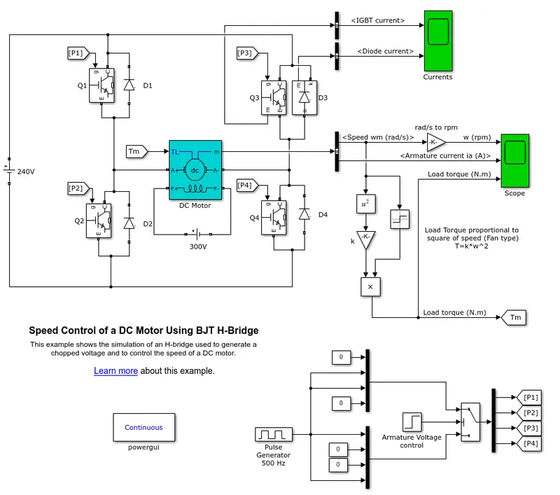
Here, the pulse generator is used to generate pulses which are fed to the four IGBTs to create pulse width modulation. In this model , the simulation is such that the motor starts in the positive direction with a duty cycle of 75% (when converted it is 180v). Scope shows motor speed, armature current and load torque. Initially the block parameters of pulse generator block are as follows:
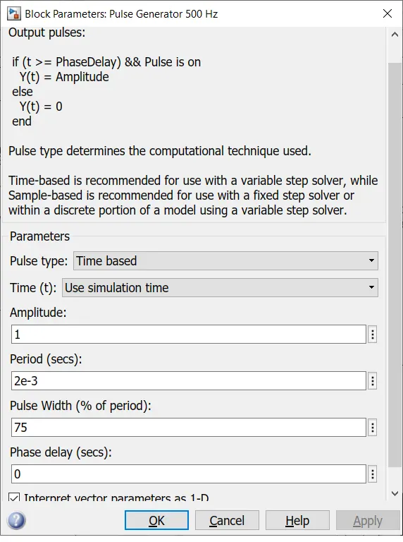
When we run the Model,we get the following results -->
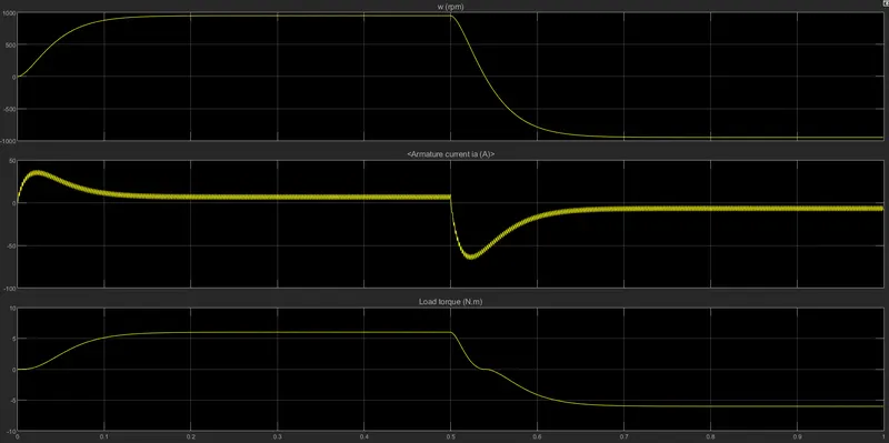
Here, in the output scope , In the first half cycle that is t=0.5secs the motor attains a speed of 1000rpm and in the next cycle armature current is reversed with the motor running in the negetive direction.Load torque is 6 Nm and in the next half cycle it is -6 Nm . Here the armature current does get shoots up. To prevent this ,we have to reduce the pulse width.
Modifying pulse width:
Now we have to change the puse width(% of period) to 40. By clicking the pulse generator block.
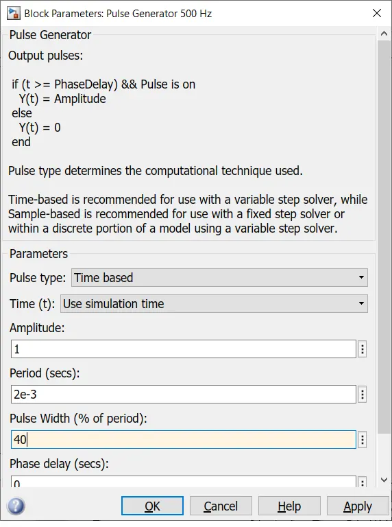
After changing the pulse width(% of period) we get the following results.
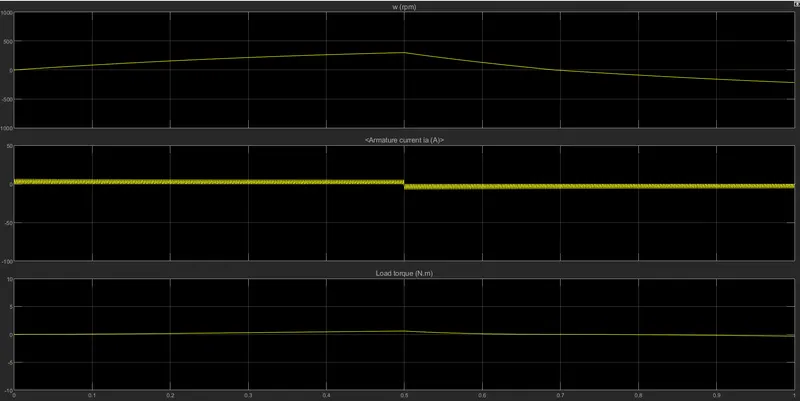
Here we observe that , the motor speed is reduced to 300 rpm and the load torque is 0.6 Nm. The armature current is almosst 0 A ,it means that the current doesn't shootup at 40% pulse width. It shows that as we reduce the pulse width,the motor speed and torque is also reduced and it can also be zero if we reduce the width more.
STUDY-2:
Refer to help section of 'The Four-quadrant Chopper DC Drive (DC7) block'. Compare it with H-bridge model.
The four quadrant DC chopper DC Drive(DC7) block -
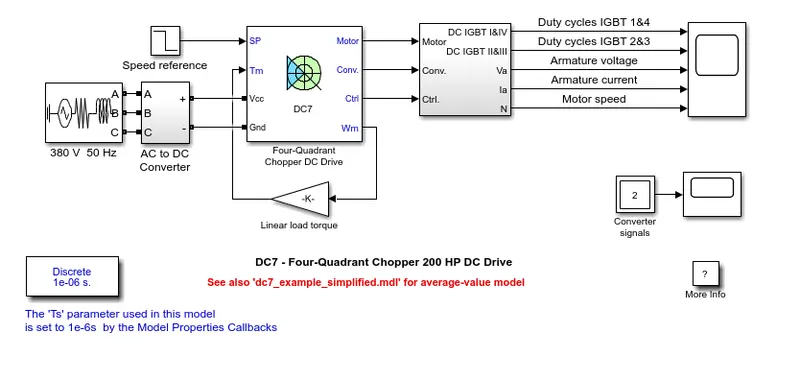
The 200HP DC motor is separately excited with a constant 150V DC field voltage source.The armature voltage is provided by an IGBT converter controlled by 2 PI regulators. The converters is fed by a 515V DC bus obtained by a rectification of a 380 V AC 50Hz voltage source. In oder to limit the DC voltage during dynamic braking mode, a braking chopper has been added between the diode rectifier and the DC7 block.
The first regulator is a speed regulator, followed by a current regulator. The speed regulator outputs the armature current reference (is p.u) used by the current controller in order to obtain the electro-magnetic torque nedded to reach the desired speed. The speed refernce change rate follows acceleration and deacceleration ramps in order to avoid sudden reference changes that could cause armature over-current and destabilizes the system. The current regulator controls the armature current by computing the appropriate duty ratios of the 5KHz pulses of the four IGBT devices (pulse width modulation). For prpoer system behaviour, the instateneous pulse values of IGBT devices 1 and 4 are opposite to those of IGBT devices 2 and 3. This generates the average armaturte voltage needed to obtain the desired armature current. In ored to limit the amplitude of the current oscillations, a smoothing inductance is placed in series with the armature circuit.
Comparision of Four-quadrant DC Drive block(DC7) block with BJT-H bridge
- In DC7 Drive block, The speed reference input is used to change the direction of the motor rotation whereas in BJT_H Bridge model, the polarity is reversed to change the direction of motor rotation.
- PI(proportional integral) controllers are used in speed and current control in DC7 block and it is not present in BJT-H bridge model.
- The DC7 block operates in four modes which are Forward motoring, Forward regerative braking, reverse motoring and reverse regerative braking whereas BJT-H bridge model operates in two modes which are Forward and reverse.
- In DC7 block speed refernce values can be changed to control the motor whereas in BJT-h bridge model the motor can be controlled by changing the pulse width of the pulse generator.
- In BJT-H bridge model the current and disturbances is high because of switching losses and the DC7 block uses ramp to avoid current shootup and for stability.
- So, therefore Four quadrant chopper DC drive is better than BJT-H bridge model.
STUDY-3:
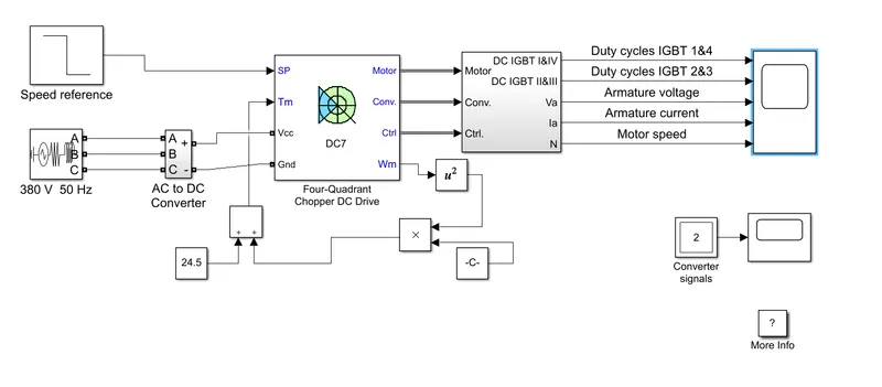
To make a suitable EV model,we need to modify DC7 block using Library Browser.
This is the example model of a DC7-Four Quadrant chopper 200HP DC Drive in the matlab help section.
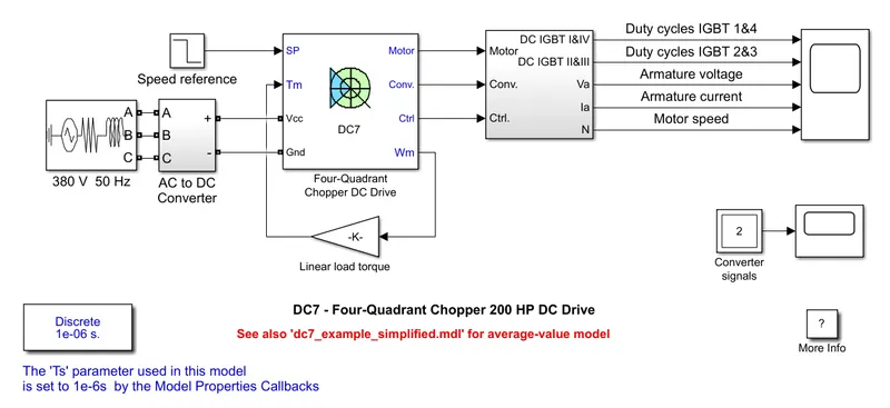
Here the linear Load-torque will be replaced with a subsystem equation according to the given load characteristics Which is
Tr = 24.7+0.0051*w^2
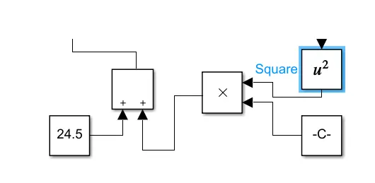
So, now we select the subsystem blocks by selecting constant, product, Sum and square fuction from math operation blocks and we replace the 'Linear load torque' block and after adding the model looks like this:
Running the simulation after replacing the "Linear load torque " with vehicle load characterictics equation i.e "Tr = 24.7 + 0.0015*w^2", we get the following output:
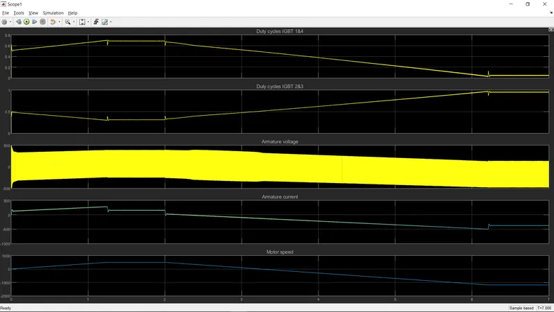
- The duty cycle plot of IGBT 1and 4 shows similar relation as that of motor speed,it increases during acceleration and decreses during deacceleration.
- The duty cycle of IGBT2 and 3 shows opposite relation to IGBT 1 and 4
- The armature voltage increases with increasing speed and decreases with decreasing speed, The average armature voltage remains constant throughout the operation and experiences a negligible change.
STUDY-4:
BRUSHLESS DC MOTOR AND ITS OPERATION
In Brushless DC motor permanent magnets attach to the rotor. The current-carrying conductors or armature windings are located in the stator. They used electrical commutation to convert electrical energy into mechanical energy. The main design difference between a brushed and brushless motors is the replacement of mechanical commutator wuth an electric switch circuit. A BLDC motor is a type of synchronous motor in the sense that the magnetic field generated by the stator and the rotor revolve at the same frequency.
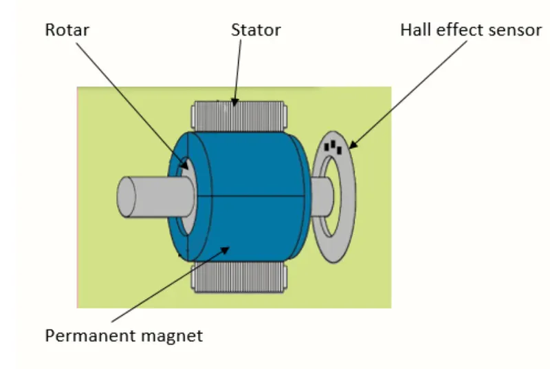
WORKING PRINCIPLE:
BLDC motor works on the principle similar to that a BRUSHED DC motor. The lorentz force law which states that whenever a current carrying conductor placed in a magnetic field it experiences a force.As a consequence of reaction force, the magnet will experience an equall and opposite force. In the BLDC motor, the current carrying conductor is stationary and the permanent magnet is moving. When the stator coils get a supply from source, it becomes electromagnet and starts producing the uniform field in the air gap. Through the source of supply is DC, switching makes to generate an AC voltage waveform with trapezoidal shape. Due to the force of interaction between electromagnet stator and permanent magnet rotor, the rotor continues to rotate. With the switching of winding as high and low signals, corresponding winding energized as north and south poles. The permanent magnet rotor with north and south poles align with stator poles which causes the motor to rotate.