Week-7 Challenge: DC Motor Control
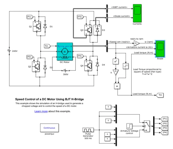
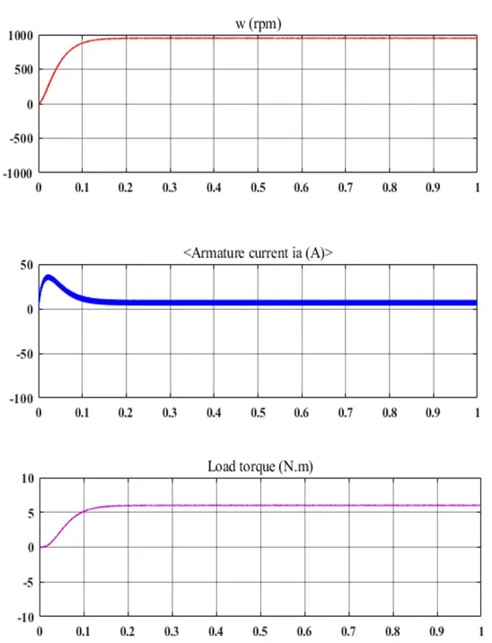
Question 1: Run MATLAB demo ‘Speed control of a DC motor using BJT H-bridge’. Modify the model such that armature current doesn’t shoot up when motor changes direction from forward to reverse.
Solution 1: In the given model the speed of motor is controlled using BJT H-bridge. The Bipolar Junction Transistor (BJT) when used for power switching applications operates as an IGBT. When it is conducting (BJT operating in the saturated region), a forward voltage Vf is developed between collector and emitter (in the range of 1 V). Therefore, the IGBT block can be used to model the BJT device.
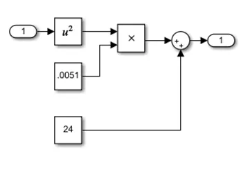
The IGBT block does not simulate the gate current controlling the BJT or IGBT. The switch is controlled by a Simulink signal (1/0). The DC motor uses the preset model (5 HP 24V 1750 rpm). It simulates a fan type load (where Load torque is proportional to square of speed). The armature means voltage can be varied from 0 to 240 V when the duty cycle (specified in the Pulse Generator block) is varied from 0 to 100%.
The H-bridge consists of four BJT/Diode pairs (BJT simulated by IGBT models). Two transistors are switched simultaneously: Q1 and Q4 or Q2 and Q3. When Q1 and Q4 are fired, a positive voltage is applied to the motor and diodes D2-D3 operate as free-wheeling diodes when Q1 and Q4 are switched off. When Q2 and Q3 are fired, a negative voltage is applied to the motor and diodes D1-D4 operate as free-wheeling diodes when Q2 and Q3 are switched off.
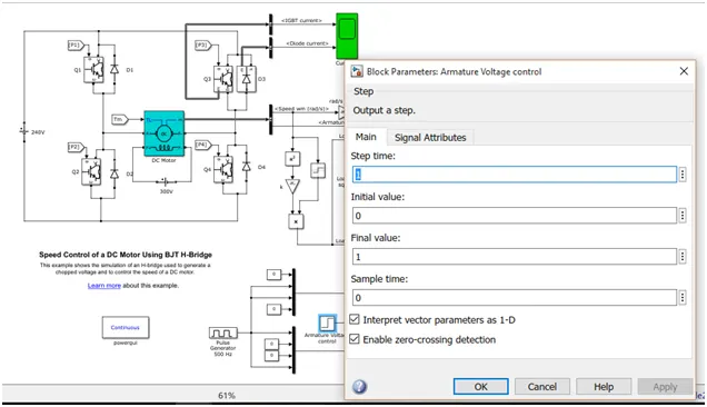
Shoot up of armature current when motor change be from forward to reverse braking can be control by increase the step size of armature voltage control signal block.
Question 2: Refer to help section of ‘The Four-Quadrant Chopper DC Drive (DC7) block’. Compare it with H-bridge model.
Solution 2: Comparison
Four Quadrant Chopper DC Drive (DC7) uses IGBT as switching device where as BJT switching device is used in BJT-H bridge model.
A three phase supply is given in DC7 model where as DC source is given BJT-H bridge model.
Motor is separately excited in BJT-H bridge model where as in DC7 model motor is not separately excited.
DC7 can operate in all four quadrants where as BJT-H model operates in two quadrant.
Question 3: Make a suitable EV model using DC7 block and make result report.
Solution 3:
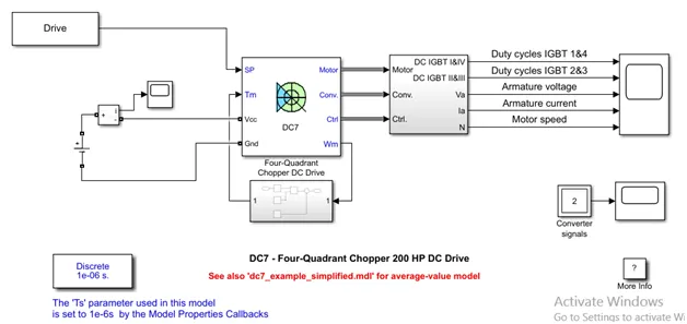
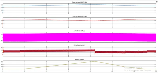
As per result shown in the below figure it can be seen that there is a linear increase in the motor speed graph. From 0 to5 sec the motor speed is zero since the value in drive cycle is zero at 5 sec the speed is increased gradually and reach maximum at 21 sec and the afterward decease gradually and reaches 0 by the end. With change in speed we can see that there is variation in armature current. As the speed incease the armature current also inceases.
Question 4: Explain in a brief about operation of BLDC motor.
Solution 4: A brushless DC motor (also known as a BLDC motor or BL motor) is an electronically commuted DC Motor which does not have brushes. The controller provides pulses of current to the motor windings which control the speed and torque of the Synchronous motor.
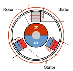
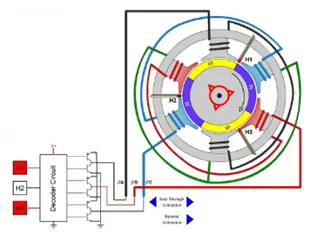
These types of motors are highly efficient in producing a large amount of torque over a vast speed range. In brushless motors, permanent magnets rotate around a fixed armature and overcome the problem of connecting current to the armature. Commutation with electronics has a large scope of capabilities and flexibility. They are known for smooth operation and holding torque when stationary. Brushless DC motor has only two basic parts: rotor and the stator. The rotor is the rotating part and has rotor magnets whereas stator is the stationary part and contains stator windings. In BLDC permanent magnets are attached in the rotor and move the electromagnets to the stator. The high power transistors are used to activate electromagnets for the shaft turns. The controller performs power distribution by using a solid-state circuit.
Before explaining the working of a brushless DC motor, it is better to understand the function of a brushed motor. In brushes motors, there are permanent magnets on the outside and a spinning armature which contains electromagnet is inside. These electromagnets create a magnetic field in the armature when the power is switched on and help to rotate the armature.
The brushes change the polarity of the pole to keep the rotation on of the armature. The basic working principle for the brushed DC motor and for brushless DC motor is same i.e. internal shaft position feedback.
A brushless DC motor is essentially flipped inside out, eliminating the need for brushes to flip the electromagnetic field. In brushless DC motors, the permanent magnets are on the rotor, and the electromagnets are on the stator. A computer then charges the electromagnets in the stator to rotate the rotor a full 360-degrees.